ºÝºÝߣ

ºÝºÝߣShare a Scribd company logo
ERROR DETECTION
RAJ VARDHAN
WHAT IS ERROR IN NETWORKING
The data link layer is responsible for the reliable transmission of data frames between two
directly connected nodes over a physical medium, such as ethernet or wi-fi.
Errors in the data link layer refer to the corruption or loss of data during this transmission
process. There are several types of errors that can occur at the data link layer.
Bit Errors Frame Loss
Frame
Duplication
Frame Mis
ordering
Frame
Corruption
Collision
TYPES OF ERROR
Single bit error:
• In a frame, there is only one bit, anywhere though, which is corrupt.
Multiple bits error:
• Frame is received with more than one bits in corrupted state.
Burst error:
• Frame contains more than 1 consecutive bits corrupted
SINGLE BIT ERROR
Single-bit error does not appear more likely in serial data transmission. For example,
sender sends the data at 10 mbps, this means that the bit lasts only for 1 ‘s and for a
single-bit error to occurred, a noise must be more than 1 ‘s.
Single-bit error mainly occurs in parallel data transmission. For example, if eight wires
are used to send the eight bits of a byte, if one of the wire is noisy, then single-bit is
corrupted per byte.
WAYS TO CHECK
Parity bit: in a parity bit scheme, an additional bit is added to each byte
or character to make the total number of ones either even (even parity) or
odd (odd parity). The receiver can then check if the number of ones in the
received data matches the expected parity, thus detecting single-bit errors.
Checksum: checksums involve performing a mathematical calculation on the
data and sending the result along with the data. The receiver recalculates
the checksum and compares it to the received value. If they don't match, an
error is detected.
MULTIPLE-BIT ERRORS
A multiple-bit error occurs when more than one bit in a data frame is changed during
transmission.
These errors are more likely to go undetected by simple error detection techniques like
parity bit and checksum.
However, more advanced techniques like cyclic redundancy check (CRC) can still be
effective in detecting multiple-bit errors.
WAYS TO CHECK
Cyclic Redundancy Check (CRC): CRC is a powerful error
detection technique that uses polynomial codes to
generate a checksum. The receiver performs the same
calculation and checks whether the received CRC matches
the calculated CRC. CRC is capable of detecting a wide
range of errors, including multiple-bit errors.
BURST ERRORS
Burst errors are consecutive errors that occur within a short span of time. These
errors are typically caused by factors like signal fading, interference, or noise
that affect a group of adjacent bits. Burst errors can be particularly problematic,
as they can cause significant data corruption.
WAYS TO CHECK
Hamming code: hamming codes are error-correcting codes that add
redundant bits to the data. These codes are designed to correct single-bit
errors and detect multiple-bit errors. They are particularly effective at
correcting burst errors of a certain length.
Interleaving: interleaving involves rearranging the data bits before
transmission so that consecutive bits are separated by a fixed distance. This
helps to spread out burst errors and reduces the likelihood of multiple
errors affecting adjacent bits.
ERROR DETECTING TECHNIQUES
Single parity
check
Two-
dimensional
parity check
Checksum
Cyclic
redundancy
check
SINGLE BIT PARITY ERROR DETECTION
Parity bit is a simple error detection
technique commonly used to detect single-bit
errors in data transmission. It involves adding
an extra bit, known as the parity bit, to the
original data before transmission. The parity
bit is set to either 0 or 1, depending on
whether the total number of 1s in the data
(including the parity bit) is meant to be even
(even parity) or odd (odd parity).
Even
Parity
Odd
Parity
EVEN PARITY CHECKING
If the total number of 1s in the data (including the parity bit) is an even
number, the parity bit is set to 0. This ensures that the total number of 1s
remains even.
If a single bit is flipped during transmission, it will result in an odd number
of 1s in the received data. The parity check at the receiving end will then
detect this error, as the total number of 1s will no longer be even.
ODD PARITY CHECKING
If the total number of 1s in the data (including the parity bit) is an odd
number, the parity bit is set to 1. This ensures that the total number of 1s
remains odd.
If a single bit is flipped during transmission, it will result in an even
number of 1s in the received data. The parity check at the receiving end
will then detect this error, as the total number of 1s will no longer be
odd.
Error Detection in Data link layer or Transport layer
TWO-DIMENSIONAL PARITY CHECK
Performance can be improved by using Two-Dimensional Parity Check which organizes
the data in the form of a table.
Parity check bits are computed for each row, which is equivalent to the single-parity check.
In Two-Dimensional Parity check, a block of bits is divided into rows, and the redundant
row of bits is added to the whole block.
At the receiving end, the parity bits are compared with the parity bits computed from the
received data.
Error Detection in Data link layer or Transport layer
CHECKSUM
Checksum Generator
• A Checksum is generated at the sending side. Checksum generator subdivides the data into
equal segments of n bits each, and all these segments are added together by using one's
complement arithmetic. The sum is complemented and appended to the original data, known as
checksum field. The extended data is transmitted across the network.
Checksum Checker
• A Checksum is verified at the receiving side. The receiver subdivides the incoming data into
equal segments of n bits each, and all these segments are added together, and then this sum is
complemented. If the complement of the sum is zero, then the data is accepted otherwise data
is rejected.
Error Detection in Data link layer or Transport layer
EXAMPLE
Suppose that the sender wants to send 4 frames each of 8 bits, where the frames are 11001100, 10101010, 11110000
and 11000011.The sender adds the bits using 1s complement arithmetic. While adding two numbers using 1s complement
arithmetic, if there is a carry over, it is added to the sum.
The sender adds the bits using 1s complement arithmetic. While adding two numbers using 1s complement arithmetic, if there
is a carry over, it is added to the sum.
After adding all the 4 frames, the sender complements the sum to get the checksum, 11010011, and sends it along with the
data frames.
The receiver performs 1s complement arithmetic sum of all the frames including the checksum. The result is complemented and
found to be 0. Hence, the receiver assumes that no error has occurred.
Error Detection in Data link layer or Transport layer
CYCLIC REDUNDANCY CHECK (CRC)
In CRC technique, a string of n 0s is appended to the data unit, and this n number is less than the
number of bits in a predetermined number, known as division which is n+1 bits.
Secondly, the newly extended data is divided by a divisor using a process is known as binary
division. The remainder generated from this division is known as CRC remainder.
Thirdly, the CRC remainder replaces the appended 0s at the end of the original data. This newly
generated unit is sent to the receiver.
The receiver receives the data followed by the CRC remainder. The receiver will treat this whole unit
as a single unit, and it is divided by the same divisor that was used to find the CRC remainder.
Error Detection in Data link layer or Transport layer
CRC GENERATOR
A CRC generator uses a modulo-2 division. Firstly, three zeroes are appended at the end of the data as the length of
the divisor is 4 and we know that the length of the string 0s to be appended is always one less than the length of the
divisor.
Now, the string becomes 11100000, and the resultant string is divided by the divisor 1001.
The remainder generated from the binary division is known as CRC remainder. The generated value of the CRC
remainder is 111.
CRC remainder replaces the appended string of 0s at the end of the data unit, and the final string would be
11100111 which is sent across the network.
CRC CHECKER
The functionality of the CRC checker is similar to the CRC generator.
When the string 11100111 is received at the receiving end, then CRC checker performs
the modulo-2 division.
A string is divided by the same divisor, i.e., 1001.
In this case, CRC checker generates the remainder of zero. Therefore, the data is
accepted.
Error Detection in Data link layer or Transport layer

More Related Content

Similar to Error Detection in Data link layer or Transport layer (20)

Error correction and detection th
Error correction and detection thError correction and detection th
Error correction and detection th
ShardaSalunkhe1
Ìý
Error detection and correction of computer network
Error detection and correction of computer networkError detection and correction of computer network
Error detection and correction of computer network
ranjana dalwani
Ìý
Error detection.
Error detection.Error detection.
Error detection.
Wasim Akbar
Ìý
Satellite error detection and correction presentation
Satellite error detection and correction presentationSatellite error detection and correction presentation
Satellite error detection and correction presentation
AhmedMuhumed2
Ìý
Error detection and correction
Error detection and correctionError detection and correction
Error detection and correction
Sisir Ghosh
Ìý
Error detection.ppt
Error detection.pptError detection.ppt
Error detection.ppt
PawanRaj48
Ìý
Error correction error detection in digital communication
Error correction error detection in digital communicationError correction error detection in digital communication
Error correction error detection in digital communication
swatihalunde
Ìý
4_Datalink__Error_Detection_and Correction.pdf
4_Datalink__Error_Detection_and Correction.pdf4_Datalink__Error_Detection_and Correction.pdf
4_Datalink__Error_Detection_and Correction.pdf
kenilpatel65
Ìý
data link layer - Chapter 3
data link layer - Chapter 3data link layer - Chapter 3
data link layer - Chapter 3
SakthiVinoth78
Ìý
error detection.ppt
error detection.ppterror detection.ppt
error detection.ppt
Jayaprasanna4
Ìý
901325_chapter vvvvvvvvvvvjjjjjjjvvv.ppt
901325_chapter vvvvvvvvvvvjjjjjjjvvv.ppt901325_chapter vvvvvvvvvvvjjjjjjjvvv.ppt
901325_chapter vvvvvvvvvvvjjjjjjjvvv.ppt
SofienBoutaib
Ìý
901325_chapter 10 (1).ppt
901325_chapter 10 (1).ppt901325_chapter 10 (1).ppt
901325_chapter 10 (1).ppt
BezaAlem2
Ìý
Error Detection and Correction.ppt
Error Detection and Correction.pptError Detection and Correction.ppt
Error Detection and Correction.ppt
KumarVaibhav100
Ìý
Error detection and correction.ppt
Error detection and correction.pptError detection and correction.ppt
Error detection and correction.ppt
MsSJeyalakshmiVelsUn
Ìý
Error.pdf
Error.pdfError.pdf
Error.pdf
IvyRamosCaones
Ìý
computer Networks Error Detection and Correction.ppt
computer Networks Error Detection and Correction.pptcomputer Networks Error Detection and Correction.ppt
computer Networks Error Detection and Correction.ppt
Jayaprasanna4
Ìý
22BA013 IM.pptx
22BA013 IM.pptx22BA013 IM.pptx
22BA013 IM.pptx
JananiHepta
Ìý
Unit 4 data link layer
Unit 4 data link layerUnit 4 data link layer
Unit 4 data link layer
mekind
Ìý
1.4.pdf 1.4.pdf 1.4.pdf1.4.pdf1.4.pdf1.4.pdf
1.4.pdf 1.4.pdf 1.4.pdf1.4.pdf1.4.pdf1.4.pdf1.4.pdf 1.4.pdf 1.4.pdf1.4.pdf1.4.pdf1.4.pdf
1.4.pdf 1.4.pdf 1.4.pdf1.4.pdf1.4.pdf1.4.pdf
gagansaigudi
Ìý
Cs8591 Computer Networks
Cs8591 Computer NetworksCs8591 Computer Networks
Cs8591 Computer Networks
Kathirvel Ayyaswamy
Ìý
Error correction and detection th
Error correction and detection thError correction and detection th
Error correction and detection th
ShardaSalunkhe1
Ìý
Error detection and correction of computer network
Error detection and correction of computer networkError detection and correction of computer network
Error detection and correction of computer network
ranjana dalwani
Ìý
Error detection.
Error detection.Error detection.
Error detection.
Wasim Akbar
Ìý
Satellite error detection and correction presentation
Satellite error detection and correction presentationSatellite error detection and correction presentation
Satellite error detection and correction presentation
AhmedMuhumed2
Ìý
Error detection and correction
Error detection and correctionError detection and correction
Error detection and correction
Sisir Ghosh
Ìý
Error detection.ppt
Error detection.pptError detection.ppt
Error detection.ppt
PawanRaj48
Ìý
Error correction error detection in digital communication
Error correction error detection in digital communicationError correction error detection in digital communication
Error correction error detection in digital communication
swatihalunde
Ìý
4_Datalink__Error_Detection_and Correction.pdf
4_Datalink__Error_Detection_and Correction.pdf4_Datalink__Error_Detection_and Correction.pdf
4_Datalink__Error_Detection_and Correction.pdf
kenilpatel65
Ìý
data link layer - Chapter 3
data link layer - Chapter 3data link layer - Chapter 3
data link layer - Chapter 3
SakthiVinoth78
Ìý
error detection.ppt
error detection.ppterror detection.ppt
error detection.ppt
Jayaprasanna4
Ìý
901325_chapter vvvvvvvvvvvjjjjjjjvvv.ppt
901325_chapter vvvvvvvvvvvjjjjjjjvvv.ppt901325_chapter vvvvvvvvvvvjjjjjjjvvv.ppt
901325_chapter vvvvvvvvvvvjjjjjjjvvv.ppt
SofienBoutaib
Ìý
901325_chapter 10 (1).ppt
901325_chapter 10 (1).ppt901325_chapter 10 (1).ppt
901325_chapter 10 (1).ppt
BezaAlem2
Ìý
Error Detection and Correction.ppt
Error Detection and Correction.pptError Detection and Correction.ppt
Error Detection and Correction.ppt
KumarVaibhav100
Ìý
Error detection and correction.ppt
Error detection and correction.pptError detection and correction.ppt
Error detection and correction.ppt
MsSJeyalakshmiVelsUn
Ìý
computer Networks Error Detection and Correction.ppt
computer Networks Error Detection and Correction.pptcomputer Networks Error Detection and Correction.ppt
computer Networks Error Detection and Correction.ppt
Jayaprasanna4
Ìý
22BA013 IM.pptx
22BA013 IM.pptx22BA013 IM.pptx
22BA013 IM.pptx
JananiHepta
Ìý
Unit 4 data link layer
Unit 4 data link layerUnit 4 data link layer
Unit 4 data link layer
mekind
Ìý
1.4.pdf 1.4.pdf 1.4.pdf1.4.pdf1.4.pdf1.4.pdf
1.4.pdf 1.4.pdf 1.4.pdf1.4.pdf1.4.pdf1.4.pdf1.4.pdf 1.4.pdf 1.4.pdf1.4.pdf1.4.pdf1.4.pdf
1.4.pdf 1.4.pdf 1.4.pdf1.4.pdf1.4.pdf1.4.pdf
gagansaigudi
Ìý

Recently uploaded (20)

GREEN BULIDING PPT FOR THE REFRENACE.PPT
GREEN BULIDING PPT FOR THE REFRENACE.PPTGREEN BULIDING PPT FOR THE REFRENACE.PPT
GREEN BULIDING PPT FOR THE REFRENACE.PPT
kamalkeerthan61
Ìý
US Patented ReGenX Generator, ReGen-X Quatum Motor EV Regenerative Accelerati...
US Patented ReGenX Generator, ReGen-X Quatum Motor EV Regenerative Accelerati...US Patented ReGenX Generator, ReGen-X Quatum Motor EV Regenerative Accelerati...
US Patented ReGenX Generator, ReGen-X Quatum Motor EV Regenerative Accelerati...
Thane Heins NOBEL PRIZE WINNING ENERGY RESEARCHER
Ìý
15. Smart Cities Big Data, Civic Hackers, and the Quest for a New Utopia.pdf
15. Smart Cities Big Data, Civic Hackers, and the Quest for a New Utopia.pdf15. Smart Cities Big Data, Civic Hackers, and the Quest for a New Utopia.pdf
15. Smart Cities Big Data, Civic Hackers, and the Quest for a New Utopia.pdf
NgocThang9
Ìý
Taykon-Kalite belgeleri
Taykon-Kalite belgeleriTaykon-Kalite belgeleri
Taykon-Kalite belgeleri
TAYKON
Ìý
CFOT Fiber Optics FOA CERTIFICATION.pptx
CFOT Fiber Optics FOA CERTIFICATION.pptxCFOT Fiber Optics FOA CERTIFICATION.pptx
CFOT Fiber Optics FOA CERTIFICATION.pptx
MohamedShabana37
Ìý
Integration of Additive Manufacturing (AM) with IoT : A Smart Manufacturing A...
Integration of Additive Manufacturing (AM) with IoT : A Smart Manufacturing A...Integration of Additive Manufacturing (AM) with IoT : A Smart Manufacturing A...
Integration of Additive Manufacturing (AM) with IoT : A Smart Manufacturing A...
ASHISHDESAI85
Ìý
Turbocor Product and Technology Review.pdf
Turbocor Product and Technology Review.pdfTurbocor Product and Technology Review.pdf
Turbocor Product and Technology Review.pdf
Totok Sulistiyanto
Ìý
Indian Soil Classification System in Geotechnical Engineering
Indian Soil Classification System in Geotechnical EngineeringIndian Soil Classification System in Geotechnical Engineering
Indian Soil Classification System in Geotechnical Engineering
Rajani Vyawahare
Ìý
G8 mini project for alcohol detection and engine lock system with GPS tracki...
G8 mini project for  alcohol detection and engine lock system with GPS tracki...G8 mini project for  alcohol detection and engine lock system with GPS tracki...
G8 mini project for alcohol detection and engine lock system with GPS tracki...
sahillanjewar294
Ìý
Piping-and-pipeline-calculations-manual.pdf
Piping-and-pipeline-calculations-manual.pdfPiping-and-pipeline-calculations-manual.pdf
Piping-and-pipeline-calculations-manual.pdf
OMI0721
Ìý
Cyber Security_ Protecting the Digital World.pptx
Cyber Security_ Protecting the Digital World.pptxCyber Security_ Protecting the Digital World.pptx
Cyber Security_ Protecting the Digital World.pptx
Harshith A S
Ìý
Air pollution is contamination of the indoor or outdoor environment by any ch...
Air pollution is contamination of the indoor or outdoor environment by any ch...Air pollution is contamination of the indoor or outdoor environment by any ch...
Air pollution is contamination of the indoor or outdoor environment by any ch...
dhanashree78
Ìý
decarbonization steel industry rev1.pptx
decarbonization steel industry rev1.pptxdecarbonization steel industry rev1.pptx
decarbonization steel industry rev1.pptx
gonzalezolabarriaped
Ìý
CONTRACTOR ALL RISK INSURANCESAR (1).ppt
CONTRACTOR ALL RISK INSURANCESAR (1).pptCONTRACTOR ALL RISK INSURANCESAR (1).ppt
CONTRACTOR ALL RISK INSURANCESAR (1).ppt
suaktonny
Ìý
Water Industry Process Automation & Control Monthly - March 2025.pdf
Water Industry Process Automation & Control Monthly - March 2025.pdfWater Industry Process Automation & Control Monthly - March 2025.pdf
Water Industry Process Automation & Control Monthly - March 2025.pdf
Water Industry Process Automation & Control
Ìý
Wireless-Charger presentation for seminar .pdf
Wireless-Charger presentation for seminar .pdfWireless-Charger presentation for seminar .pdf
Wireless-Charger presentation for seminar .pdf
AbhinandanMishra30
Ìý
Frankfurt University of Applied Science urkunde
Frankfurt University of Applied Science urkundeFrankfurt University of Applied Science urkunde
Frankfurt University of Applied Science urkunde
Lisa Emerson
Ìý
TM-ASP-101-RF_Air Press manual crimping machine.pdf
TM-ASP-101-RF_Air Press manual crimping machine.pdfTM-ASP-101-RF_Air Press manual crimping machine.pdf
TM-ASP-101-RF_Air Press manual crimping machine.pdf
ChungLe60
Ìý
IPC-9716_2024 Requirements for Automated Optical Inspection (AOI) Process Con...
IPC-9716_2024 Requirements for Automated Optical Inspection (AOI) Process Con...IPC-9716_2024 Requirements for Automated Optical Inspection (AOI) Process Con...
IPC-9716_2024 Requirements for Automated Optical Inspection (AOI) Process Con...
ssuserd9338b
Ìý
decarbonization steel industry rev1.pptx
decarbonization steel industry rev1.pptxdecarbonization steel industry rev1.pptx
decarbonization steel industry rev1.pptx
gonzalezolabarriaped
Ìý
GREEN BULIDING PPT FOR THE REFRENACE.PPT
GREEN BULIDING PPT FOR THE REFRENACE.PPTGREEN BULIDING PPT FOR THE REFRENACE.PPT
GREEN BULIDING PPT FOR THE REFRENACE.PPT
kamalkeerthan61
Ìý
15. Smart Cities Big Data, Civic Hackers, and the Quest for a New Utopia.pdf
15. Smart Cities Big Data, Civic Hackers, and the Quest for a New Utopia.pdf15. Smart Cities Big Data, Civic Hackers, and the Quest for a New Utopia.pdf
15. Smart Cities Big Data, Civic Hackers, and the Quest for a New Utopia.pdf
NgocThang9
Ìý
Taykon-Kalite belgeleri
Taykon-Kalite belgeleriTaykon-Kalite belgeleri
Taykon-Kalite belgeleri
TAYKON
Ìý
CFOT Fiber Optics FOA CERTIFICATION.pptx
CFOT Fiber Optics FOA CERTIFICATION.pptxCFOT Fiber Optics FOA CERTIFICATION.pptx
CFOT Fiber Optics FOA CERTIFICATION.pptx
MohamedShabana37
Ìý
Integration of Additive Manufacturing (AM) with IoT : A Smart Manufacturing A...
Integration of Additive Manufacturing (AM) with IoT : A Smart Manufacturing A...Integration of Additive Manufacturing (AM) with IoT : A Smart Manufacturing A...
Integration of Additive Manufacturing (AM) with IoT : A Smart Manufacturing A...
ASHISHDESAI85
Ìý
Turbocor Product and Technology Review.pdf
Turbocor Product and Technology Review.pdfTurbocor Product and Technology Review.pdf
Turbocor Product and Technology Review.pdf
Totok Sulistiyanto
Ìý
Indian Soil Classification System in Geotechnical Engineering
Indian Soil Classification System in Geotechnical EngineeringIndian Soil Classification System in Geotechnical Engineering
Indian Soil Classification System in Geotechnical Engineering
Rajani Vyawahare
Ìý
G8 mini project for alcohol detection and engine lock system with GPS tracki...
G8 mini project for  alcohol detection and engine lock system with GPS tracki...G8 mini project for  alcohol detection and engine lock system with GPS tracki...
G8 mini project for alcohol detection and engine lock system with GPS tracki...
sahillanjewar294
Ìý
Piping-and-pipeline-calculations-manual.pdf
Piping-and-pipeline-calculations-manual.pdfPiping-and-pipeline-calculations-manual.pdf
Piping-and-pipeline-calculations-manual.pdf
OMI0721
Ìý
Cyber Security_ Protecting the Digital World.pptx
Cyber Security_ Protecting the Digital World.pptxCyber Security_ Protecting the Digital World.pptx
Cyber Security_ Protecting the Digital World.pptx
Harshith A S
Ìý
Air pollution is contamination of the indoor or outdoor environment by any ch...
Air pollution is contamination of the indoor or outdoor environment by any ch...Air pollution is contamination of the indoor or outdoor environment by any ch...
Air pollution is contamination of the indoor or outdoor environment by any ch...
dhanashree78
Ìý
decarbonization steel industry rev1.pptx
decarbonization steel industry rev1.pptxdecarbonization steel industry rev1.pptx
decarbonization steel industry rev1.pptx
gonzalezolabarriaped
Ìý
CONTRACTOR ALL RISK INSURANCESAR (1).ppt
CONTRACTOR ALL RISK INSURANCESAR (1).pptCONTRACTOR ALL RISK INSURANCESAR (1).ppt
CONTRACTOR ALL RISK INSURANCESAR (1).ppt
suaktonny
Ìý
Wireless-Charger presentation for seminar .pdf
Wireless-Charger presentation for seminar .pdfWireless-Charger presentation for seminar .pdf
Wireless-Charger presentation for seminar .pdf
AbhinandanMishra30
Ìý
Frankfurt University of Applied Science urkunde
Frankfurt University of Applied Science urkundeFrankfurt University of Applied Science urkunde
Frankfurt University of Applied Science urkunde
Lisa Emerson
Ìý
TM-ASP-101-RF_Air Press manual crimping machine.pdf
TM-ASP-101-RF_Air Press manual crimping machine.pdfTM-ASP-101-RF_Air Press manual crimping machine.pdf
TM-ASP-101-RF_Air Press manual crimping machine.pdf
ChungLe60
Ìý
IPC-9716_2024 Requirements for Automated Optical Inspection (AOI) Process Con...
IPC-9716_2024 Requirements for Automated Optical Inspection (AOI) Process Con...IPC-9716_2024 Requirements for Automated Optical Inspection (AOI) Process Con...
IPC-9716_2024 Requirements for Automated Optical Inspection (AOI) Process Con...
ssuserd9338b
Ìý
decarbonization steel industry rev1.pptx
decarbonization steel industry rev1.pptxdecarbonization steel industry rev1.pptx
decarbonization steel industry rev1.pptx
gonzalezolabarriaped
Ìý

Error Detection in Data link layer or Transport layer

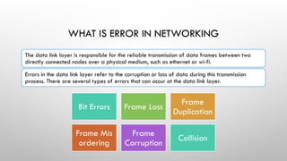
  • 2. WHAT IS ERROR IN NETWORKING The data link layer is responsible for the reliable transmission of data frames between two directly connected nodes over a physical medium, such as ethernet or wi-fi. Errors in the data link layer refer to the corruption or loss of data during this transmission process. There are several types of errors that can occur at the data link layer. Bit Errors Frame Loss Frame Duplication Frame Mis ordering Frame Corruption Collision
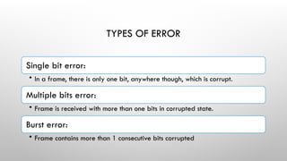
  • 3. TYPES OF ERROR Single bit error: • In a frame, there is only one bit, anywhere though, which is corrupt. Multiple bits error: • Frame is received with more than one bits in corrupted state. Burst error: • Frame contains more than 1 consecutive bits corrupted
  • 4. SINGLE BIT ERROR Single-bit error does not appear more likely in serial data transmission. For example, sender sends the data at 10 mbps, this means that the bit lasts only for 1 ‘s and for a single-bit error to occurred, a noise must be more than 1 ‘s. Single-bit error mainly occurs in parallel data transmission. For example, if eight wires are used to send the eight bits of a byte, if one of the wire is noisy, then single-bit is corrupted per byte.
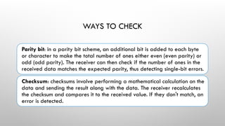
  • 5. WAYS TO CHECK Parity bit: in a parity bit scheme, an additional bit is added to each byte or character to make the total number of ones either even (even parity) or odd (odd parity). The receiver can then check if the number of ones in the received data matches the expected parity, thus detecting single-bit errors. Checksum: checksums involve performing a mathematical calculation on the data and sending the result along with the data. The receiver recalculates the checksum and compares it to the received value. If they don't match, an error is detected.
  • 6. MULTIPLE-BIT ERRORS A multiple-bit error occurs when more than one bit in a data frame is changed during transmission. These errors are more likely to go undetected by simple error detection techniques like parity bit and checksum. However, more advanced techniques like cyclic redundancy check (CRC) can still be effective in detecting multiple-bit errors.
  • 7. WAYS TO CHECK Cyclic Redundancy Check (CRC): CRC is a powerful error detection technique that uses polynomial codes to generate a checksum. The receiver performs the same calculation and checks whether the received CRC matches the calculated CRC. CRC is capable of detecting a wide range of errors, including multiple-bit errors.
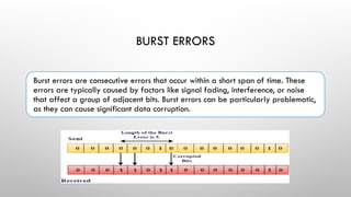
  • 8. BURST ERRORS Burst errors are consecutive errors that occur within a short span of time. These errors are typically caused by factors like signal fading, interference, or noise that affect a group of adjacent bits. Burst errors can be particularly problematic, as they can cause significant data corruption.
  • 9. WAYS TO CHECK Hamming code: hamming codes are error-correcting codes that add redundant bits to the data. These codes are designed to correct single-bit errors and detect multiple-bit errors. They are particularly effective at correcting burst errors of a certain length. Interleaving: interleaving involves rearranging the data bits before transmission so that consecutive bits are separated by a fixed distance. This helps to spread out burst errors and reduces the likelihood of multiple errors affecting adjacent bits.
  • 10. ERROR DETECTING TECHNIQUES Single parity check Two- dimensional parity check Checksum Cyclic redundancy check
  • 11. SINGLE BIT PARITY ERROR DETECTION Parity bit is a simple error detection technique commonly used to detect single-bit errors in data transmission. It involves adding an extra bit, known as the parity bit, to the original data before transmission. The parity bit is set to either 0 or 1, depending on whether the total number of 1s in the data (including the parity bit) is meant to be even (even parity) or odd (odd parity). Even Parity Odd Parity
  • 12. EVEN PARITY CHECKING If the total number of 1s in the data (including the parity bit) is an even number, the parity bit is set to 0. This ensures that the total number of 1s remains even. If a single bit is flipped during transmission, it will result in an odd number of 1s in the received data. The parity check at the receiving end will then detect this error, as the total number of 1s will no longer be even.
  • 13. ODD PARITY CHECKING If the total number of 1s in the data (including the parity bit) is an odd number, the parity bit is set to 1. This ensures that the total number of 1s remains odd. If a single bit is flipped during transmission, it will result in an even number of 1s in the received data. The parity check at the receiving end will then detect this error, as the total number of 1s will no longer be odd.
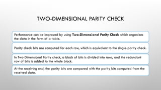
  • 15. TWO-DIMENSIONAL PARITY CHECK Performance can be improved by using Two-Dimensional Parity Check which organizes the data in the form of a table. Parity check bits are computed for each row, which is equivalent to the single-parity check. In Two-Dimensional Parity check, a block of bits is divided into rows, and the redundant row of bits is added to the whole block. At the receiving end, the parity bits are compared with the parity bits computed from the received data.
  • 17. CHECKSUM Checksum Generator • A Checksum is generated at the sending side. Checksum generator subdivides the data into equal segments of n bits each, and all these segments are added together by using one's complement arithmetic. The sum is complemented and appended to the original data, known as checksum field. The extended data is transmitted across the network. Checksum Checker • A Checksum is verified at the receiving side. The receiver subdivides the incoming data into equal segments of n bits each, and all these segments are added together, and then this sum is complemented. If the complement of the sum is zero, then the data is accepted otherwise data is rejected.
  • 19. EXAMPLE Suppose that the sender wants to send 4 frames each of 8 bits, where the frames are 11001100, 10101010, 11110000 and 11000011.The sender adds the bits using 1s complement arithmetic. While adding two numbers using 1s complement arithmetic, if there is a carry over, it is added to the sum. The sender adds the bits using 1s complement arithmetic. While adding two numbers using 1s complement arithmetic, if there is a carry over, it is added to the sum. After adding all the 4 frames, the sender complements the sum to get the checksum, 11010011, and sends it along with the data frames. The receiver performs 1s complement arithmetic sum of all the frames including the checksum. The result is complemented and found to be 0. Hence, the receiver assumes that no error has occurred.
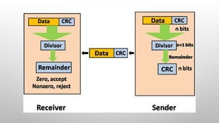
  • 21. CYCLIC REDUNDANCY CHECK (CRC) In CRC technique, a string of n 0s is appended to the data unit, and this n number is less than the number of bits in a predetermined number, known as division which is n+1 bits. Secondly, the newly extended data is divided by a divisor using a process is known as binary division. The remainder generated from this division is known as CRC remainder. Thirdly, the CRC remainder replaces the appended 0s at the end of the original data. This newly generated unit is sent to the receiver. The receiver receives the data followed by the CRC remainder. The receiver will treat this whole unit as a single unit, and it is divided by the same divisor that was used to find the CRC remainder.
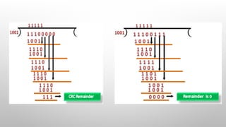
  • 23. CRC GENERATOR A CRC generator uses a modulo-2 division. Firstly, three zeroes are appended at the end of the data as the length of the divisor is 4 and we know that the length of the string 0s to be appended is always one less than the length of the divisor. Now, the string becomes 11100000, and the resultant string is divided by the divisor 1001. The remainder generated from the binary division is known as CRC remainder. The generated value of the CRC remainder is 111. CRC remainder replaces the appended string of 0s at the end of the data unit, and the final string would be 11100111 which is sent across the network.
  • 24. CRC CHECKER The functionality of the CRC checker is similar to the CRC generator. When the string 11100111 is received at the receiving end, then CRC checker performs the modulo-2 division. A string is divided by the same divisor, i.e., 1001. In this case, CRC checker generates the remainder of zero. Therefore, the data is accepted.