DC motors have excellent speed and torque control characteristics and are often used to drive pumps and in transportation applications. A DC motor operates on the principle that a current-carrying conductor in a magnetic field experiences a force. It consists of a rotor that spins inside a stator. DC motors convert electrical energy into mechanical energy. The types of DC motors include shunt-wound, series-wound, and compound-wound motors, which have different characteristics related to torque, speed, and efficiency. The speed and direction of a DC motor can be controlled by varying the current in the field windings or armature. Losses include copper, iron, friction, and brush contact losses.
Presentation of Electrical Engineering ( Maximum Power Transfer Theorem )MohitRaghav19
?
The Maximum Power Transfer Theorem states that maximum power is transferred to a load when the load resistance equals the Thevenin equivalent resistance of the circuit. The document outlines the theorem's proof, steps for application, efficiency calculations, and real-world applications such as in audio systems and automobile engines, while also noting its limitations in efficiency, typically capping at 50%. It emphasizes that the theorem is not suitable for applications where higher efficiency is critical.
The document discusses amplifiers with feedback, explaining the concepts of positive and negative feedback. Positive feedback increases amplifier gain but often leads to distortions and instability, making it rare in amplifiers, while negative feedback reduces gain yet offers benefits like lowered distortion and enhanced stability. It outlines the principles of negative voltage feedback in amplifiers and provides a brief mathematical example.
The document discusses transmission line impedance and input impedance. It defines characteristic impedance as the ratio of voltage to current waves travelling along a transmission line. It provides expressions for characteristic impedance in terms of line parameters R, L, G, C. It then derives expressions for input impedance of open circuit, short circuit, matched and mismatched lossless transmission lines. It shows that input impedance is capacitive for a short open circuit line and inductive for a short circuit line.
The document contains 4 solved questions related to power systems.
1. It provides the step-by-step solution to draw the pu impedance diagram for a power system network including a generator, motor, and two transformers.
2. It calculates the terminal voltage of a synchronous machine in a radial transmission system with given component ratings and loads.
3. It determines the EMF and angle of a synchronous generator operating at a given power factor and current into an infinite bus.
4. It calculates the line current for a 3-phase, 3-wire star-connected unbalanced load using given impedance values connected to each phase.
AM Radio Receiver with Automatic Gain Control UnitCem Recai ??rak
?
This document summarizes the design and implementation of an AM radio receiver circuit with an automatic gain control (AGC) unit. It includes:
- A block diagram of the full circuit including an antenna, tuned filter, peak detector, AGC unit, RF amplifier, audio amplifier, and loudspeaker.
- Descriptions of each circuit block, including simulations of the tuned filter, peak detector, RF amplifier, and audio amplifier.
- Issues encountered in implementing the peak detector, AGC unit, and audio amplifier circuits experimentally that differed from simulations.
- An overview of the experimental setup and limitations encountered with certain circuit elements like the peak detector time constant and heating in the audio amplifier transistors.
Cycloconverters are used to convert AC power directly to AC power of variable magnitude and frequency. They have four main advantages over conventional AC to DC to AC conversion: they do not require an intermediate DC link, allow bidirectional power flow, can produce high quality sine waves at low frequencies without filters, and are line commutated without a separate commutation circuit. Cycloconverters are commonly used to drive large induction and synchronous motors at frequencies from 0-20Hz, such as in cement mill, ship propulsion, rolling mill, and mine applications. However, they have disadvantages of not allowing smooth stepless frequency control, producing more distortion at low frequencies, and having a more complex control circuit design.
This document provides an overview and summary of different load flow analysis methods. It begins with an introduction to load flow studies and the power flow equations. It then summarizes three classical iterative methods: Gauss-Seidel, Newton-Raphson, and Fast Decoupled. The document also briefly discusses other optimization methods like fuzzy logic, genetic algorithms, and particle swarm optimization that can be applied to load flow problems. Case studies are presented at the end to demonstrate the different techniques.
Elect principles 2 dc transients (inductive)sdacey
?
When an emf is applied to an inductor, the current cannot rise instantly due to the back emf generated by the coil, which opposes the flow of current. As the current rises in an inductance, the back emf causes the rate of rise in current to reduce over time. Similarly, when the source is removed, the energy stored in the magnetic field cannot cause the current to fall immediately to zero due to the self-induced back emf.
Simulation based minor project on Buck converter( DC to Dc step down Converter)Ashutosh Singh
?
This document summarizes a simulation project report on a buck converter (DC to DC step down converter) completed by three students. The report includes an introduction to buck converters, the circuit diagram and working of the buck converter, component selection including calculations for the inductor and capacitor, the simulation model used, results of the simulation, and applications of buck converters.
This document provides an introduction to switched-capacitor circuits. It discusses:
1) How switched-capacitor circuits sample input signals using capacitors and switches to create discrete-time systems, unlike continuous-time systems.
2) Key considerations for sampling switches including speed, precision, and input signal range limitations.
3) Common switched-capacitor circuit topologies like amplifiers, integrators, and common-mode feedback that replace resistors with capacitors and switches.
Speed control of IM using Space Vector ModulationAsif Jamadar
?
This document presents a project on controlling the speed of a three-phase induction motor using space vector pulse width modulation (SVPWM). It discusses the aims of developing a simulation and prototype model for V/f speed control. It describes different PWM techniques and speed control methods for induction motors. It also explains the concepts of space vector modulation including voltage vectors, reference vectors, sector selection, and duty cycle calculation. The hardware and software implementation are outlined, including the inverter design, gate driver circuit, and MATLAB simulation model. Test results demonstrate varying the motor speed by adjusting the voltage and frequency while maintaining a constant V/f ratio.
Communication Systems_B.P. Lathi and Zhi Ding (Lecture No 4-9)Adnan Zafar
?
The document provides an overview of fundamental concepts in communication systems, focusing on the nature and classification of signals, including continuous-time and discrete-time signals, analog and digital signals. It discusses the properties of energy and power signals, correlation functions, and introduces key mathematical tools like Fourier series and transforms. Additionally, it explores signal operations, the representation of signals in vector spaces, and the significance of orthogonality in signal analysis.
DIRECT TORQUE CONTROL OF THREE PHASE INDUCTION MOTOR USING FOUR SWITCH THREE ...smadhumitha
?
This document discusses direct torque control of a three-phase induction motor using a four-switch inverter. It begins by reviewing existing literature on direct torque control methods and their limitations. The author then proposes using direct torque control with space vector modulation to control a four-switch inverter for improved dynamic response, reduced torque ripple, and lower harmonic distortion compared to existing methods. Simulation and hardware results demonstrate the benefits of the proposed method, such as lower torque ripple and current harmonic distortion.
The document discusses different measures for quantifying the size of signals, including signal energy (Eg) which is defined as the integral of the signal amplitude squared and incorporates both amplitude and duration, and signal power (Pg) which is used for signals that do not approach zero at infinity and is defined as the time average of the signal amplitude squared. Examples are provided to illustrate calculating energy for a signal that approaches zero at infinity and power for a periodic signal whose power exists.
The document describes the specifications of various logic integrated circuits (ICs), including their fan-in, fan-out, input, and output characteristics. It defines common digital IC terminology related to voltage levels, current parameters, propagation delays, and noise immunity. It then examines the characteristics of different logic families, specifically TTL and CMOS. TTL families include standard TTL, low power TTL, high speed TTL, and others. CMOS families include 4000 series and 74C/HC/HCT series. Key specifications like voltage levels, noise margins, and power dissipation are compared between TTL and CMOS logic families.
RF Module Design - [Chapter 8] Phase-Locked LoopsSimen Li
?
This document discusses the design of RF transceiver modules focusing on frequency synthesis and phase-locked loops. It covers various frequency synthesis techniques, the impact of phase noise on signal integrity, and the significance of loop analysis regarding stability and settling time. The analysis includes different architectures for PLLs, direct analog and digital synthesis, and their respective advantages in generating accurate frequency outputs.
The document discusses differential amplifiers, which amplify the difference between two input voltages, and details three types: one op-amp, two op-amps, and three op-amps configurations. It explains the output voltage expressions for these amplifiers, focusing on their voltage gains and circuit designs. Additionally, it highlights how using more op-amps can improve gain and input resistance in differential amplifier designs.
This document discusses the continuous-time Fourier transform. It begins by developing the Fourier transform representation of aperiodic signals as the limit of Fourier series coefficients as the period increases. It then defines the Fourier transform pairs and discusses properties like convergence. Several examples of calculating the Fourier transform of common signals like exponentials, pulses and periodic signals are provided. Key concepts like the sinc function are also introduced.
This document discusses different classes of power amplifiers:
- Class A amplifiers have constant current flow and output varies over the full input cycle. Maximum efficiency is 25%.
- Class B amplifiers have current flow for only half the input cycle. They require a push-pull configuration of two transistors to generate the full output cycle. Maximum efficiency is 78.5%.
- Class AB operates between classes A and B with output between 180-360 degrees.
- Class C has output for less than half the cycle and requires a resonant load circuit. It has the highest efficiency but also the highest distortion.
This document discusses plane electromagnetic waves. It defines plane waves as waves whose wavefronts are infinite parallel planes of constant amplitude normal to the phase velocity vector. The electric and magnetic fields of a plane wave are perpendicular to each other and to the direction of propagation. Plane waves can be linearly, circularly, or elliptically polarized depending on the orientation and behavior of the electric field vector over time. Linear polarization occurs when the electric field is oriented along a fixed line. Circular polarization results when the electric field traces out a circle, and elliptical polarization is characterized by an elliptical trace.
The document summarizes the synchronous machine. It describes how synchronous machines can operate as generators or motors and are used in large power applications. The rotor rotates at a constant synchronous speed and its magnetic field rotates in sync with the stator magnetic field. Common applications include power generation, pumps, timers and mills. The document then focuses on the synchronous generator, describing its construction, types of rotors and windings, voltage generation process, equivalent circuit model and phasor diagrams under different load conditions. An example problem is also included to illustrate voltage and current calculations.
This document describes an experiment to build an analog PID controller circuit using op-amps. It includes:
1. An introduction to the basic concepts of proportional, integral and derivative control and how they are implemented using op-amps.
2. Analysis of the circuit diagrams for differential input, derivative, and integrator op-amps used to build the PID controller.
3. Procedures to assemble the circuit, test it using a function generator and oscilloscope, and calculate gains.
4. Results showing the input-output signal relationships for each component, along with calculated gains and pole locations. Square and sine wave responses are shown for the complete PID controller.
5. A conclusion that the
The document discusses different types of filters including passive and active filters. It provides information on symmetrical T and Pi networks and their properties. It defines electronic filters and describes their functions of removing or enhancing frequency components. It also discusses different filter types such as low pass, high pass, band pass and band elimination filters. Finally, it describes active filters and lists common types as Butterworth, Chebyshev, Bessel and Elliptical filters, providing some of their advantages.
This document summarizes a presentation on FIR and IIR filter design techniques. It introduces common IIR filter design methods like impulse invariance and bilinear transformation. It also discusses FIR filter design using window functions, frequency sampling, and minimizing mean squared error. Specific window functions are examined, including rectangular, triangular, Hanning, Hamming, Kaiser, and Blackman windows. The document provides an overview of digital filter design topics and serves as a reference for further exploration of FIR and IIR filter design methods.
The document provides an in-depth overview of multistage amplifiers in electronic circuit analysis, detailing configurations like cascade, cascode, and Darlington arrangements with examples. It discusses the calculation of overall gain from interconnected amplifiers and includes references for further study. Key aspects covered are design principles, output resistance, input resistance, and small-signal voltage gain calculations for these amplifier configurations.
This document provides an introduction to transistors and MOSFETs. It begins by describing the invention of the transistor in 1947 and defining what a transistor is. It then discusses the main types of transistors - BJT and FET, including MOSFET and JFET. The rest of the document focuses on MOSFETs, explaining what they are, their terminals and symbols, types of MOSFETs like n-MOSFET and p-MOSFET, and how MOSFETs work and are fabricated through processes like photolithography, etching, diffusion, and oxidation. It includes diagrams of MOSFET structure and operation. In the end it briefly discusses CMOS fabrication process flow.
Bipolar junction transistors (BJTs) are three-terminal semiconductor devices consisting of two pn junctions. There are two types, NPN and PNP, depending on the order of doping. BJTs can operate as amplifiers and switches by controlling the flow of majority charge carriers through the base terminal. Proper biasing is required to operate the transistor in its active region between cutoff and saturation. Common configurations include common-base, common-emitter, and common-collector, each with different input and output characteristics. Maximum ratings like power dissipation and voltages must be considered for circuit design and temperature derating.
A MOSFET (Metal Oxide Semiconductor Field Effect Transistor) is a semiconductor device that is commonly used in power electronics. It works by modulating charge concentration between a gate electrode, which is insulated from other device regions by an oxide layer, and a body region. Depending on whether it is an n-channel or p-channel MOSFET, the source and drain regions have either n+ or p+ doping while the body has the opposite doping. Applying a voltage to the gate can turn the channel between source and drain on or off to allow or prevent current flow. MOSFETs can be made with silicon on insulator or other semiconductor materials.
The document discusses different types of field effect transistors (FETs), including junction FETs (JFETs), metal-oxide-semiconductor FETs (MOSFETs), and metal-semiconductor FETs (MESFETs). It focuses on the structure and operation of n-channel and p-channel MOSFETs, describing how a positive or negative gate voltage is used to create a conducting channel. Scaling challenges for MOSFETs are also discussed, along with new materials needed like high-k dielectrics and metal gates, and approaches like silicon-on-insulator (SOI) technology.
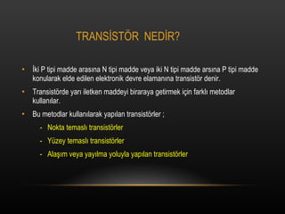
2. TRANS?ST?R NED?R? ?ki P tipi madde aras?na N tipi madde veya iki N tipi madde ars?na P tipi madde konularak elde edilen elektronik devre elaman?na transist?r denir. Transist?rde yar? iletken maddeyi biraraya getirmek i?in farkl? metodlar kullan?lar. Bu metodlar kullan?larak yap?lan transist?rler ; - Nokta temasl? transist?rler - Y®πzey temasl? transist?rler - Ala??m veya yay?lma yoluyla yap?lan transist?rler
3. Genelde elektronik devrelerde y®πzey temasl? transist?rler kullan?l?r. Y®πzey temasl? transist?rler ise ; - NPN transist?r - PNP transist?r lerdir
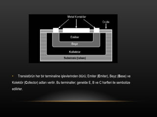
4. Transist?r®πn her bir terminaline i?levlerinden ?t®πr®π; Emiter ( E miter), Beyz ( B ase) ve Kolekt?r ( C ollector) adlar? verilir. Bu terminaller; genelde E, B ve C harfleri ile sembolize edilirler.
5. B?R TRANS?ST?R?N ?AL??MAS? ???N GEREKL? ?ARTLAR Transist?r®πn ?al??abilmesi i?in; beyz-emiter jonksiyonu do?ru y?nde, beyzkolekt?r jonksiyonu ise ters y?nde polarmaland?r?lmal?d?r. Bu ?al??ma bi?imine transist?r®πn aktif b?lgede ?al??mas? denir.
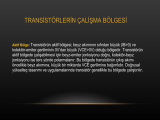
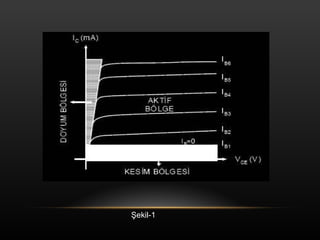
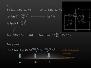
7. TRANS?ST?RLER?N ?AL??MA B?LGES? Aktif B?lge : Transist?r®πn aktif b?lgesi; beyz ak?m?n?n s?f?rdan b®πy®πk (IB>0) ve kolekt?r-emiter geriliminin 0V°Ødan b®πy®πk (VCE>0V) oldu?u b?lgedir. Transist?r®πn aktif b?lgede ?al??abilmesi i?in beyz-emiter jonksiyonu do?ru, kolekt?r-beyz jonksiyonu ise ters y?nde polarmalan?r. Bu b?lgede transist?r®πn ??k?? ak?m? ?ncelikle beyz ak?m?na, k®π?®πk bir miktarda VCE gerilimine ba??ml?d?r. Do?rusal y®πkselte? tasar?m? ve uygulamalar?nda transist?r genellikle bu b?lgede ?al??t?r?l?r.
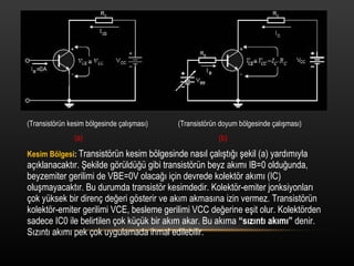
8. (Transist?r®πn kesim b?lgesinde ?al??mas?) (Transist?r®πn doyum b?lgesinde ?al??mas?) (a) (b) Kesim B?lgesi : Transist?r®πn kesim b?lgesinde nas?l ?al??t??? ?ekil (a) yard?m?yla a??klanacakt?r. ?ekilde g?r®πld®π?®π gibi transist?r®πn beyz ak?m? IB=0 oldu?unda, beyzemiter gerilimi de VBE=0V olaca?? i?in devrede kolekt?r ak?m? (IC) olu?mayacakt?r. Bu durumda transist?r kesimdedir. Kolekt?r-emiter jonksiyonlar? ?ok y®πksek bir diren? de?eri g?sterir ve ak?m akmas?na izin vermez. Transist?r®πn kolekt?r-emiter gerilimi VCE, besleme gerilimi VCC de?erine e?it olur. Kolekt?rden sadece IC0 ile belirtilen ?ok k®π?®πk bir ak?m akar. Bu ak?ma °∞s?z?nt? ak?m?°± denir. S?z?nt? ak?m? pek ?ok uygulamada ihmal edilebilir.
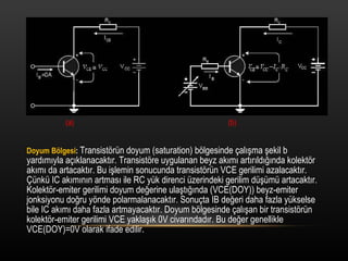
9. (a) (b) Doyum B?lgesi : Transist?r®πn doyum (saturation) b?lgesinde ?al??ma ?ekil b yard?m?yla a??klanacakt?r. Transist?re uygulanan beyz ak?m? art?r?ld???nda kolekt?r ak?m? da artacakt?r. Bu i?lemin sonucunda transist?r®πn VCE gerilimi azalacakt?r. ?®πnk®π IC ak?m?n?n artmas? ile RC y®πk direnci ®πzerindeki gerilim d®π?®πm®π artacakt?r. Kolekt?r-emiter gerilimi doyum de?erine ula?t???nda (VCE(DOY)) beyz-emiter jonksiyonu do?ru y?nde polarmalanacakt?r. Sonu?ta IB de?eri daha fazla y®πkselse bile IC ak?m? daha fazla artmayacakt?r. Doyum b?lgesinde ?al??an bir transist?r®πn kolekt?r-emiter gerilimi VCE yakla??k 0V civar?ndad?r. Bu de?er genellikle VCE(DOY)=0V olarak ifade edilir.
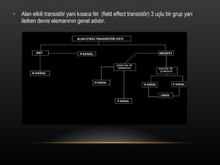
12. Alan etkili transist?r yani k?saca fet (field effect transist?r) 3 u?lu bir grup yar? iletken devre eleman?n?n genel ad?d?r.
13. Alan etkili transist?r ; jonksiyon fet (JFET) yada metal oksitli yar? iletken JFET (MOSFET) olarak ismilendirilir. Her iki tip transist?r®πnde n ve p kanall? olmak ®πzere iki ?e?idi bulunmaktad?r. N kanall? transist?rlerde iletim , elektronlarla P kanall? transist?rlerde ise bo?luklarla(hole) sa?lan?r.
14. FETLER?N ?ZELL?KLER? G®πr®πlt®π (parazit) oranlar? ?ok d®π?®πkt®πr. Ak?mlar? ?s? ile fazla de?i?mez. Giri? ve ??k?? empedanslar? al?ak frekanslarda ?ok y®πksektir. Ancak, ?al??ma frekanslar? y®πkseldik?e bu de?er d®π?er.
15. KULLANIM ALANLARI Osilat?rler, al?c? ve vericilerinradyofrekans ve al?ak frekansradyofrekans ve al?ak frekanskatlar?, VHF y®πkselte?ler, ?l?®πkatlar?, VHF y®πkselte?ler, ?l?®πaletleri, mikserler, otomatik kazan?aletleri, mikserler, otomatik kazan?kontrol devreleri vb.kontrol devreleri vb.
17. JFET YAP?S? VE ?AL??MAS? JFET 3 uca sahiptir. U?lar?na i?levlerinden ?t®πr®π Gate , Source ve Drain isimleri verilmi?tir. JFET sembol®πnde gate ucunda bulunan okun y?n®π transist?r®πm®πz®πn n veya p kanall? oldu?unu g?sterir. Ok y?n®π i?eri do?ruysa n kanall? JFET , d??ar? do?ruysa p kanall? JFET olarak isimlendirilir.
18. Ge?it(gate) : n- tipi ?ubu?un sa? ve sol yanlar?nda bir pn eklemi olu?turmak i?in dispersiyon veya bir ba?ka y?ntemle yo?un bir ?ekilde al?c? atomlar?yla katk?lanm?? b?lgedir. Kaynak(source ) : ?o?unluk y®πk ta??y?c?lar?n?n yar? ileyken ?ubu?a girdikleri u?tur. Aka?(drain) :?o?unluk y®πk ta??y?c?lar?n?n yar? iletken ?ubu?u terk ettikleri u?tur. Kanal : ?ki ge?it aras?nda kalan ve ?o?unluk y®πk ta??y?c?lar?n?n kaynaktan aka?a ge?tikleri b?lgeye denir.
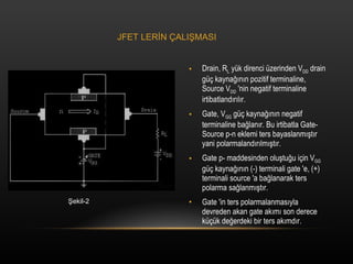
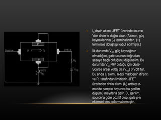
19. Drain, R L y®πk direnci ®πzerinden V DD drain g®π? kayna??n?n pozitif terminaline, Source V DD 'nin negatif terminaline irtibatland?r?l?r. Gate, V GG g®π? kayna??n?n negatif terminaline ba?lan?r. Bu irtibatla Gate-Source p-n eklemi ters bayaslanm??t?r yani polarmaland?r?lm??t?r. Gate p- maddesinden olu?tu?u i?in V GG g®π? kayna??n?n (-) terminali gate 'e, (+) terminali source 'a ba?lanarak ters polarma sa?lanm??t?r. Gate 'in ters polarmalanmas?yla devreden akan gate ak?m? son derece k®π?®πk de?erdeki bir ters ak?md?r. ?ekil-2 JFET LER?N ?ALI?MASI
20. I D drain ak?m?, JFET ®πzerinde source 'den drain 'e do?ru akar. (Ak?m?n, g®π? kaynaklar?n?n (-) terminalinden, (+) terminale dola?t??? kabul edilmi?tir.) ?lk durumda V GG g®π? kayna??n?n olmad???n?, gate ucunun do?rudan ?aseye ba?l? oldu?unu d®π?®πnelim, Bu durumda V GG =0V oldu?u i?in Gate-Source aras? voltaj da (V GS ) 0 Volt 'tur. Bu anda I D ak?m?, n-tipi maddenin direnci ve R L taraf?ndan limitlenir. JFET ®πzerinden drain ak?m? (I D ) arttk?a n-madde par?as? boyunca bu gerilim d®π?®πm®π meydana gelir. Bu gerilim, source 'a g?re pozitif olup, gate p-n eklemini ters polarmalanm??t?r.
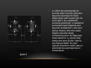
21. p-n eklemi ters polarmaland??? her durumda, eklem civar?nda; i?inde ak?m ta??y?c?lar? bulunmayan bir bo?luk b?lgesi (eklem setti) meydana gelir. Bu durum ?ekil 3 °Æde p maddelerinin ?evresinde g?sterilmi?tir. p maddelerinin ?evresindeki bo?luk b?lgesinde ak?m ta??y?c?lar? olmad???ndan I D drain ak?m? akamaz. B?ylece, drain k?sm? bo?luk b?lgeleri aras?ndaki sahada s?n?rland?r?lm?? olunur. Bu b?lge kanal olarak adland?r?l?r. V DD kaynak voltaj? artt?k?a drain ak?m? da artar. Fakat bu art?? do?rusal de?ildir. Bu art???n do?rusal olmamas?n?n nedeni, gate p-n eklemindeki ters polarmalanmas?n?n artmas?ndand?r. ?ekil-3
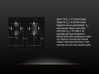
22. ?ekil 3 °Æde V DD = 4 Volt iken bo?luk b?lgesi ile V DD = 6 Volt iken bo?luk b?lgesinin durumu g?r®πlmektedir. V DD drain kaynak voltaj?n?n daha fazla artt?r?lmas? (V DD = 6V) ?ekil 3 °Æde g?r®πld®π?®π gibi bo?luk b?lgelerinin birbirine daha fazla yakla?mas?na neden olur. B?yle bir durumda drain kaynak voltajn?n daha fazla artt?r?lmas? I D drain al?m?nda ?ok az bir art?? meydana getirir.
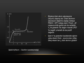
23. B?ylece drain ak?m? saturasyona (doyum) ula?m?? olur. Drain ak?m?n?n saturasyon de?erine ula?t??? noktaya PINCH - OFF noktas? denir. Pimch - off nokas?na kritik gerilim ad? da verilebilir. V P ile g?sterilir. Bu de?er n-kanall? JFET 'te negatif, p-kanall? da ise pozitif de?erdir. ?ekil 4 'te g?sterilen karakteristik e?rinin yatay ekseni Drain - source aras? voltaj?, dikey ekseni ise I D drain ak?m?n? g?sterir ?ekil-4(Ak?m ®C Gerilim karekteristi?i)
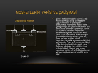
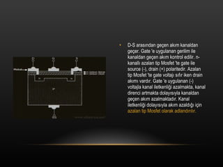
28. ?ekil 5 'te taban malzeme (g?vde) p-tipi madde al?nm??t?r. Bu p-tipi maddenin uygun yerlerinde N tipi b?lgeler olu?turulmu? ve aralar?na ince bir kanal yerle?tirilmi?tir. Bu yap?n?n ®πst®π silikon oksit tabakas? ile tamamen kaplanm??t?r. Ancak bu tabakan?n havadaki sodyumdan etkilenebilece?inden bunun ®πzeri ikinci tabaka olan silikon nitrat ile kapat?lm??t?r. N-maddelerinden ??kart?lan u?lar?n ad?; Drain ve Source u?lar?, silikon tabakalar?ndan delik a??larak metalik irtibat sa?lanm??t?r. Drain ve Source u?lar?, N-tipi b?lge ile do?rudan irtibatl? oldu?u halde Gate ucu yar?iletkenden yal?t?lm??, izole edilmi? haldedir. Burada gate ucuna uygulanan gerilim s?f?r volt oldu?unda drain ve source u?lar? aras?nda belirli bir ak?m akar. MOSFETLER?N YAP?S? VE ?AL??MAS? ?ekil-5 Azalan tip mosfet
29. ?®πnk®π, drain ve source birbiriyle irtibatl?d?r. Gate terminaline (+) gerilim uyguland???nda, N-tipi maddeler aras?nda mevcut olan kanal geni?leyece?inden D-S aras?ndan ge?en ak?m artar. Gate terminaline (-) gerilim uyguland???nda kanal daralarak ak?m azal?r. ?ekil 5 'de kanal N-tipi maddeden yap?ld??? i?in n-kanall? azalan tip Mosfet 'tir. Kanal p-tipi maddeden de yap?labilir.
30. D-S aras?ndan ge?en ak?m kanaldan ge?er. Gate 'e uygulanan gerilim ile kanaldan ge?en ak?m kontrol edilir. n-kanall? azalan tip Mosfet 'te gate ile source (-), drain (+) polaritedir. Azalan tip Mosfet 'te gate voltaj? s?f?r iken drain ak?m? vard?r. Gate 'e uygulanan (-) voltajla kanal iletkenli?i azalmakta, kanal direnci artmakta dolay?s?yla kanaldan ge?en ak?m azalmaktad?r. Kanal iletkenli?i dolay?s?yla ak?m azald??? i?in azalan tip Mosfet olarak adland?r?l?r.
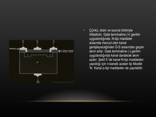
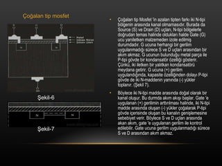
31. ?o?alan tip Mosfet 'in azalan tipten fark? iki N-tipi b?lgenin aras?nda kanal olmamas?d?r. Burada da Source (S) ve Drain (D) u?lar?, N-tipi b?lgelerle do?rudan temas halinde olduklar? halde Gate (G) ucu yar?iletken malzemeden izole edilmi? durumdad?r. G ucuna herhangi bir gerilim uygulanmad??? s®πrece S ve D u?lar? aras?ndan bir ak?m akmaz. G ucunun bulundu?u metal par?a ile P-tipi g?vde bir kondansat?r ?zelli?i g?sterir. ?®πnk®π, iki iletken bir yal?tkan kondansat?r®π meydana getirir. G ucuna (+) gerilim uyguland???nda, kapasite ?zelli?inden dolay? P-tipi g?vde de iki N-maddenin yan?nda (-) y®πkler toplan?r. (?ekil 7). B?ylece iki N-tipi madde aras?nda do?al olarak bir kanal olu?ur. Bu durmda ak?m ak??? ba?lar. Gate 'e uygulanan (+) gerilimin artt?r?lmas? halinde, iki N-tipi madde aras?nda olu?an (-) y®πkler ?o?alarak P-tipi g?vde i?erisinde olu?an bu kanal?n geni?lemesine sebebiyet verir. B?ylece S ve D u?lar? aras?nda akan ak?m, gate 'e uygulanan gerilim ile kontrol edilebilir. Gate ucuna gerilim uygulanmad??? s®πrece S ve D aras?ndan ak?m akmaz. ?o?alan tip mosfet ?ekil-6 ?ekil-7
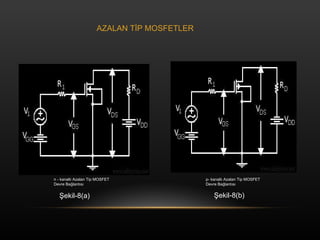
33. n - kanall? Azalan Tip MOSFET Devre Ba?lant?s? p- kanall? Azalan Tip MOSFET Devre Ba?lant?s? ?ekil-8(a) ?ekil-8(b) AZALAN T?P MOSFETLER
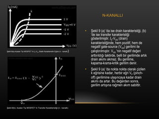
34. ?ekil 9 (a) 'da ise drain karakteristi?i, (b) 'de ise transfer karakteristi?i g?sterilmi?tir. I D -V DS (drain) karakteristi?inde, hem pozitif, hem de negatif gate-source (V GS ) gerilimi ile ?al??t?r?lm??t?r. V GS 'nin negatif de?eri artt?r?ld??? taktirde, belli bir gerilimde art?k drain ak?m? akmaz. Bu gerilime, kapama-k?sma-kritik gerilim denir. ?ekil 9 (a) 'da nokta nokta olarak ?izilen k e?risine kadar, herbir e?ri V P (pinch-off) gerilimine ula??ncaya kadar drain ak?m? da artar. Bu de?erden sonra, gerilim art???na ra?men ak?m sabittir. ?ekil-9(a)-Azalan Tip MOSFET 'in I D -V DS Statik Karakteristik E?risi (n - kanall? ) ?ekil-9(b)- Azalan Tip MOSFET 'in Transfer Karakteristi?i (n - kanall?) N-KANALLI
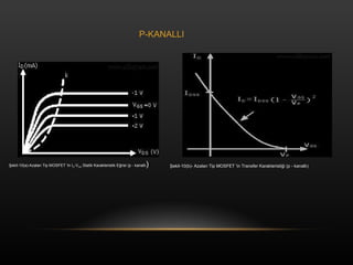
35. ?ekil-10(a)-Azalan Tip MOSFET 'in I D -V DS Statik Karakteristik E?risi (p - kanall? ) ?ekil-10(b)- Azalan Tip MOSFET 'in Transfer Karakteristi?i (p - kanall?) P-KANALLI
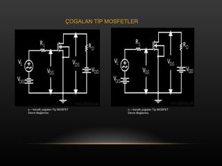
36. p ®C kanall? ?o?alan Tip MOSFET Devre Ba?lant?s? n ®C kanall? ?o?alan Tip MOSFET Devre Ba?lant?s? ?OGALAN T?P MOSFETLER
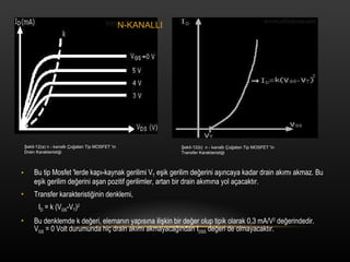
37. Bu tip Mosfet 'lerde kap?-kaynak gerilimi V T e?ik gerilim de?erini a??ncaya kadar drain ak?m? akmaz. Bu e?ik gerilim de?erini a?an pozitif gerilimler, artan bir drain ak?m?na yol a?acakt?r. Transfer karakteristi?inin denklemi, I D = k (V GS -V T ) 2 Bu denklemde k de?eri, eleman?n yap?s?na ili?kin bir de?er olup tipik olarak 0,3 mA/V 2 de?erindedir. V GS = 0 Volt durumunda hi? drain ak?m? akmayaca??ndan I DSS de?eri de olmayacakt?r. ?ekil-12(a) n - kanall? ?o?alan Tip MOSFET 'in Drain Karakteristi?i ?ekil-12(b) n - kanall? ?o?alan Tip MOSFET 'in Transfer Karakteristi?i N-KANALLI
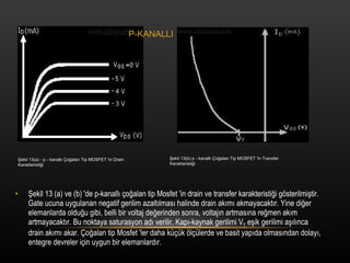
38. ?ekil 13 (a) ve (b) 'de p-kanall? ?o?alan tip Mosfet 'in drain ve transfer karakteristi?i g?sterilmi?tir. Gate ucuna uygulanan negatif gerilim azalt?lmas? halinde drain ak?m? akmayacakt?r. Yine di?er elemanlarda oldu?u gibi, belli bir voltaj de?erinden sonra, voltaj?n artmas?na re?men ak?m artmayacakt?r. Bu noktaya saturasyon ad? verilir. Kap?-kaynak gerilimi V T e?ik gerilimi a??l?nca drain ak?m? akar. ?o?alan tip Mosfet 'ler daha k®π?®πk ?l?®πlerde ve basit yap?da olmas?ndan dolay?, entegre devreler i?in uygun bir elemanlard?r. ?ekil 13(a) - p - kanall? ?o?alan Tip MOSFET 'in Drain Karakteristi?i ?ekil 13(b) p - kanall? ?o?alan Tip MOSFET 'in Transfer Karakteristi?i P-KANALLI