
Fiber alignment and joint loss
- 2. CONTENTS ď‚—Introduction ď‚—Losses due to Fresnel Reflection. ď‚—Losses due to Geometric and Optical Parameter variations. ď‚—Multimode Fiber Joints. ď‚—Single Mode Fiber Joints.
- 3. INTRODUCTION  Fiber splices: These are semipermanent or permanent joints which find major use in most optical fiber telecommunication systems (analogous to electrical soldered joints).  Demountable fiber connectors or simple connectors: These are removable joints which allow easy, fast, manual coupling and uncoupling of fibers (analogous to electrical plugs and sockets).  A crucial aspect of fiber jointing concerns the optical loss associated with the connection.  A major consideration with all types of fiber–fiber connection is the optical loss encountered at the interface.
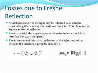
- 4. Losses due to Fresnel Reflection A small proportion of the light may be reflected back into the transmitting fiber causing attenuation at the joint. This phenomenon, known as Fresnel reflection Associated with the step changes in refractive index at the jointed interface (i.e. glass–air–glass). The magnitude of this partial reflection of the light transmitted through the interface is given by equation 1.
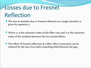
- 5. Losses due to Fresnel Reflection The loss in decibels due to Fresnel reflection at a single interface is given by equation 2. Where n1 is the refractive index of the fiber core and n is the refractive index of the medium between the two jointed fibers. The effect of Fresnel reflection at a fiber–fiber connection can be reduced by the use of an index-matching fluid between the gap.
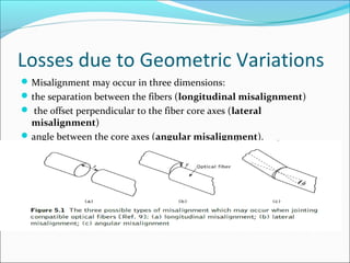
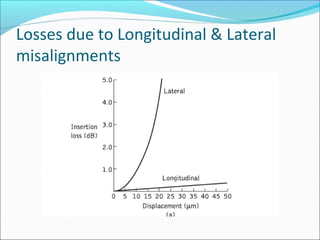
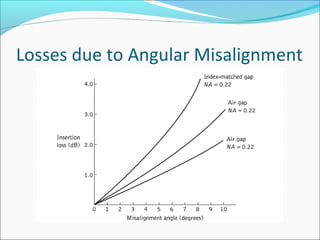
- 6. Losses due to Geometric Variations ď‚—Misalignment may occur in three dimensions: ď‚—the separation between the fibers (longitudinal misalignment) ď‚— the offset perpendicular to the fiber core axes (lateral misalignment) ď‚—angle between the core axes (angular misalignment).
- 7. Losses due to Longitudinal & Lateral misalignments
- 8. Losses due to Angular Misalignment
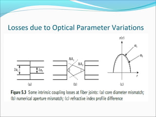
- 9. Losses due to Optical Parameter Variations ď‚—Losses at joints may occur due to the following reasons: ď‚— variations in core and/or cladding diameters. ď‚— variations in numerical apertures and/or relative refractive index differences. ď‚— variations in refractive index profiles. ď‚— fiber faults (core ellipticity, core concentricity, etc.).
- 10. Losses due to Optical Parameter Variations
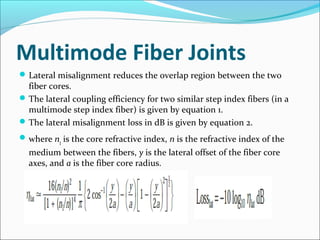
- 11. Multimode Fiber Joints ď‚—Lateral misalignment reduces the overlap region between the two fiber cores. ď‚—The lateral coupling efficiency for two similar step index fibers (in a multimode step index fiber) is given by equation 1. ď‚—The lateral misalignment loss in dB is given by equation 2. ď‚—where n1 is the core refractive index, n is the refractive index of the medium between the fibers, y is the lateral offset of the fiber core axes, and a is the fiber core radius.
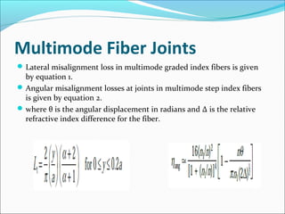
- 12. Multimode Fiber Joints Lateral misalignment loss in multimode graded index fibers is given by equation 1. Angular misalignment losses at joints in multimode step index fibers is given by equation 2. where θ is the angular displacement in radians and Δ is the relative refractive index difference for the fiber.
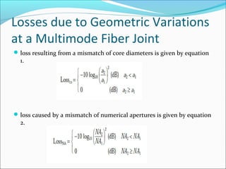
- 13. Losses due to Geometric Variations at a Multimode Fiber Joint ď‚—loss resulting from a mismatch of core diameters is given by equation 1. ď‚—loss caused by a mismatch of numerical apertures is given by equation 2.
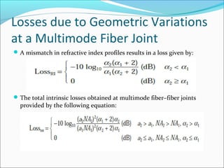
- 14. Losses due to Geometric Variations at a Multimode Fiber Joint A mismatch in refractive index profiles results in a loss given by: The total intrinsic losses obtained at multimode fiber–fiber joints provided by the following equation: