A spectrophotometer is an instrument that measures the amount of light absorbed by a sample. Spectrophotometer techniques are used to measure the concentration of solutes in solution by measuring the amount of the light that is absorbed by the solution in a cuvette placed in the spectrophotometer .
A spectrophotometer uses light to measure the concentration of solutes in solution. It works by passing light through a sample in a cuvette and measuring the amount of light absorbed. The main components are a light source, monochromator to separate wavelengths, sample cuvette, detector, and display. Common light sources are tungsten halogen lamps and xenon flash lamps. Monochromators use dispersion devices like prisms, filters, or diffraction gratings. Detectors convert light to electrical signals and displays show output. Measurements rely on Beer's Law relating absorption to concentration.
This document discusses optical filters, which selectively transmit light of certain wavelengths. It begins by introducing optical filters and their basic properties, such as long pass, short pass, and band pass filters. It then discusses key optical filter properties when using laser light sources. The document outlines different filter characteristics and types, including Fabry-Perot filters and in-fiber Bragg grating filters. Fabry-Perot filters are described as consisting of two mirrors with a cavity in between that light enters and reflects within, transmitting light in certain wavelengths. The document presents information on optical filters for optical fiber communication applications.
Microscope filters are used to filter out unnecessary light and increase the amount of light required for microscopy. There are several types of microscope filters that serve different purposes. Neutral filters decrease brightness without reducing voltage. Excitation filters select excitation wavelengths for fluorescence microscopy. Coloured filters like daylight blue increase resolution and contrast. Heat-absorbing filters prevent heat damage. Barrier filters protect from ultraviolet light and increase fluorescence brightness. Microscope filters are used to control light intensity, increase contrast and resolution, transmit selected wavelengths, and protect the eye from injury.
UV SPECTROSCOPY AND INSTRUMENTATION .INSTRUMENTAL METHODS OF ANALYSIS, B.PHARM 7TH SEM. AND FOR BSC,MSC CHEMISTRY.
This is Geeta prasad kashyap (Asst. Professor), SVITS, Bilaspur (C.G) 495001
This document describes the instrumentation of UV-Visible spectroscopy. It discusses the key components of UV-Visible spectrophotometers including radiation sources such as tungsten lamps and deuterium lamps, wavelength selectors like monochromators and filters, sample containers, and detectors. It provides detailed diagrams of the internal components and systematic design of UV-Visible spectrophotometers. Various parts of the instrument like the radiation source, sample cell, and detector are explained.
This document discusses various topics related to engineering physics, including attenuation in optical fibers, types of attenuation such as absorption, scattering and bending losses, different types of dispersion including chromatic and waveguide dispersion, and fiber optic sensors. It describes displacement sensors which measure the distance between a transmitting and receiving fiber, and pressure sensors which detect changes in interference patterns due to variations in the length of the sensing fiber under pressure changes.
Spectrophotometry is used in Biology to plot optical density curves (to determine the concentration of biochemicals) or to conduct a cell count for a suspension.
This document describes the components and design of spectrophotometry instruments. It discusses the key components including the light source, monochromator system using filters, prisms or gratings, sample holder, detector and readout. Specific light sources like tungsten-halogen lamps, hydrogen and xenon discharge lamps are covered. Requirements for an ideal light source and operating principles of filters, prisms and diffraction gratings as monochromators are summarized.
Spectrophotometry uses spectrophotometers to measure how much light is absorbed by a sample as a function of wavelength. A spectrophotometer directs light from a source through a sample and measures the amount of light transmitted. There are two main types - single beam spectrometers which measure one sample at a time, and double beam spectrometers which simultaneously measure a sample and reference. Spectrophotometers can be classified by the wavelength range used such as visible, UV, or infrared. They consist of a light source, dispersion elements, focusing elements, sample cells, detectors, and displays. Spectrophotometers are used to determine concentrations, identify compounds, and measure color.
Photographic Filter by Dr. Anjandev Biswasadritabiswas
Ìý
Filters are transparent materials that modify the light passing through camera lenses. There are three main types of filters - glass, optical resin, and gels. The filter factor indicates the amount of exposure adjustment needed to compensate for light absorbed by the filter. Common filters include polarizers, neutral density filters, and graduated neutral density filters which are used to reduce glare, extend exposure times, and control strong light gradients respectively. Special effect filters can produce effects like star bursts, soft focus, and multiple images. Filters are available in screw-in and slot-in versions to fit different lens and holder types.
This document discusses different types of optical filters used in optical communication systems. It describes four common optical filters: grating filters, arrayed waveguide grating (AWG) filters, fiber Bragg grating filters, and Fabry-Perot filters. Grating filters use diffraction gratings to spatially separate wavelengths. AWG filters use arrays of waveguides as interferometers. Fiber Bragg gratings act as reflectors for specific wavelengths due to periodic refractive index variations. Fabry-Perot filters use an optical cavity between two mirrors to selectively transmit wavelengths through interference.
Instrumentation of uv spectrophotometer pranav kumar singhAkanksha Mishra
Ìý
This document discusses the components and operation of a UV spectrophotometer. It describes the main components as the source, wavelength selector, sample container, detector, and readout. It provides details on common sources like deuterium arc lamps, tungsten lamps, and xenon arc lamps. It also discusses wavelength selector devices like monochromators and filters. The document outlines the applications of UV spectrophotometry in areas like detection of impurities, structure elucidation, and quantitative analysis. In under 3 sentences.
The document discusses the basic components, working principles, and types of light microscopes, including brightfield, darkfield, phase contrast, and fluorescence microscopes. It explains how each type of microscope functions, such as how brightfield microscopy uses a condenser lens and objective lens to illuminate samples for viewing. The document also outlines some common applications of light microscopy in fields like medicine, manufacturing, and research.
The document discusses the different types of light microscopes including bright field, dark field, phase contrast, and fluorescence microscopes and explains their basic components, working principles, and applications. Bright field microscopy is described as the most basic technique that uses a condenser and objective lens to illuminate a specimen against a bright background for viewing. The various microscope types are used across fields like medicine, industry, and research to examine cells, tissues, and small objects.
This presentation is about the monochromators and specifically their use in spectroscopy. It includes definition, principle, origin of term, principle, types, prism monochromator, diffraction grating monochromator, difference in both of them, their uses and working as well, optical filters and their uses and application.
A Monochromator is an optical device that transmits a mechanically selectable narrow band of wavelengths of light chosen from a wider range of wavelengths available at the input. And the unwanted radiations are blocked by the slit allowing only the desired ray to pass (monochromatic).
A dispersive element disperse the polychromatic light into several bands of single wavelength and then a slit is used which stops the unwanted bands of light, allowing only the desired monochromatic light to pass through its exit point.
By fixing the slit and rotating the dispersive element, the direction of the dispersed light is turned so that the colour of the resulting monochromatic light changes.
When electromagnetic radiation passes through a prism, it is refracted because the index of refraction of the prism material is different from that of air.
Shorter wavelengths are refracted more than longer wavelengths.
By rotation of the prism, different wavelengths of the spectrum can be made to pass through an exit slit and through the sample.
A prism works satisfactorily in the ultraviolet and visible regions and can also be used in the infrared region.
Because of its nonlinear dispersion, it works more effectively for the shorter wavelengths.
Glass prisms and lenses can be used in the visible region.
Quartz or fused silica must be used in the ultraviolet region.
The entire monochromatic compartment must be kept dry.
This document discusses optical fibers and fiber optic sensors. It begins with an introduction to optical fibers, including their principles, types, advantages and disadvantages. It then discusses fiber optic sensors, including their components, classifications, and uses. It focuses on displacement sensors, explaining their principles, experimental setup, results and applications. Displacement sensors can be designed using glass or plastic optical fibers with different numbers of fibers, and their sensitivity depends on the fiber material and number of fibers used.
1. A spectrophotometer measures the amount of light absorbed by a sample as a function of wavelength. It was invented in 1940 and works based on Beer's law which relates absorbance to analyte concentration, path length, and absorptivity.
2. It consists of a light source, wavelength selector such as a monochromator containing a grating or prism, sample container, detector, and display. Common light sources are tungsten lamps and deuterium arc lamps. Samples are held in plastic, glass, or quartz cuvettes.
3. Spectrophotometers can be single beam, double beam, or split beam. Double beam spectrophotometers compare sample and reference
Introduction
Definition
Basic mechanism
Prerequisite of flow cytometer
Components of flow cytometry
Flow system
Optics system
Concept of scattering
Advantage
Limitation
Application
Conclusion
References
1) A spectrophotometer uses light to measure the concentration of solutes in solution by determining how much light is absorbed.
2) It follows Beer's and Lambert's laws - absorbance is directly proportional to concentration and path length. Common applications include measuring nucleic acid concentrations and identifying organic compounds by their unique absorption spectra.
3) Key components include a light source, monochromator to separate wavelengths, cuvettes to hold samples, detectors, and displays. Spectrophotometers can be single or double beam, with double beam reducing errors from instability.
This document discusses different types of microscopy and their principles. It begins by defining a microscope and microscopy. It then explains principles of light microscopy, including magnification, resolution, numerical aperture, and illumination sources. Specific types of light microscopy are described in more detail, including brightfield microscopy, darkfield microscopy, phase contrast microscopy, differential interference contrast (DIC) microscopy, and fluorescence microscopy. Their basic optical setups and principles are summarized.
UV visible spectropy introduction and instrumentVenkatesh Mantha
Ìý
This document discusses the components and design of spectrophotometers. It describes how spectrophotometers use various components like sources, monochromators, sample holders and detectors to measure the absorption of light in the ultraviolet-visible region. Specifically, it discusses how sources like tungsten-halogen lamps emit light, how monochromators like diffraction gratings and prisms isolate wavelengths, and how detectors convert light signals into electrical signals for analysis.
Instrumentation of uv visible spectroscopyZainab&Sons
Ìý
UV-visible spectroscopy uses light in the UV and visible ranges. It works by passing light through a sample and measuring how much light is absorbed. Key components are a light source, monochromator, sample cell, detector, and recorder. For UV light a hydrogen lamp is used as the source and quartz is used for the cell and prism. It can be used to identify functional groups and conjugation, detect impurities, and determine molecular structure and in quantitative analysis. Applications include qualitative and quantitative analysis of organic compounds.
Gauges are a Pump's Best Friend - Troubleshooting and Operations - v.07Brian Gongol
Ìý
No reputable doctor would try to conduct a basic physical exam without the help of a stethoscope. That's because the stethoscope is the best tool for gaining a basic "look" inside the key systems of the human body. Gauges perform a similar function for pumping systems, allowing technicians to "see" inside the pump without having to break anything open. Knowing what to do with the information gained takes practice and systemic thinking. This is a primer in how to do that.
This PDF highlights how engineering model making helps turn designs into functional prototypes, aiding in visualization, testing, and refinement. It covers different types of models used in industries like architecture, automotive, and aerospace, emphasizing cost and time efficiency.
EXPLORE 6 EXCITING DOMAINS:
1. Machine Learning: Discover the world of AI and ML!
2. App Development: Build innovative mobile apps!
3. Competitive Programming: Enhance your coding skills!
4. Web Development: Create stunning web applications!
5. Blockchain: Uncover the power of decentralized tech!
6. Cloud Computing: Explore the world of cloud infrastructure!
Join us to unravel the unexplored, network with like-minded individuals, and dive into the world of tech!
Preface: The ReGenX Generator innovation operates with a US Patented Frequency Dependent Load Current Delay which delays the creation and storage of created Electromagnetic Field Energy around the exterior of the generator coil. The result is the created and Time Delayed Electromagnetic Field Energy performs any magnitude of Positive Electro-Mechanical Work at infinite efficiency on the generator's Rotating Magnetic Field, increasing its Kinetic Energy and increasing the Kinetic Energy of an EV or ICE Vehicle to any magnitude without requiring any Externally Supplied Input Energy. In Electricity Generation applications the ReGenX Generator innovation now allows all electricity to be generated at infinite efficiency requiring zero Input Energy, zero Input Energy Cost, while producing zero Greenhouse Gas Emissions, zero Air Pollution and zero Nuclear Waste during the Electricity Generation Phase. In Electric Motor operation the ReGen-X Quantum Motor now allows any magnitude of Work to be performed with zero Electric Input Energy.
Demonstration Protocol: The demonstration protocol involves three prototypes;
1. Protytpe #1, demonstrates the ReGenX Generator's Load Current Time Delay when compared to the instantaneous Load Current Sine Wave for a Conventional Generator Coil.
2. In the Conventional Faraday Generator operation the created Electromagnetic Field Energy performs Negative Work at infinite efficiency and it reduces the Kinetic Energy of the system.
3. The Magnitude of the Negative Work / System Kinetic Energy Reduction (in Joules) is equal to the Magnitude of the created Electromagnetic Field Energy (also in Joules).
4. When the Conventional Faraday Generator is placed On-Load, Negative Work is performed and the speed of the system decreases according to Lenz's Law of Induction.
5. In order to maintain the System Speed and the Electric Power magnitude to the Loads, additional Input Power must be supplied to the Prime Mover and additional Mechanical Input Power must be supplied to the Generator's Drive Shaft.
6. For example, if 100 Watts of Electric Power is delivered to the Load by the Faraday Generator, an additional >100 Watts of Mechanical Input Power must be supplied to the Generator's Drive Shaft by the Prime Mover.
7. If 1 MW of Electric Power is delivered to the Load by the Faraday Generator, an additional >1 MW Watts of Mechanical Input Power must be supplied to the Generator's Drive Shaft by the Prime Mover.
8. Generally speaking the ratio is 2 Watts of Mechanical Input Power to every 1 Watt of Electric Output Power generated.
9. The increase in Drive Shaft Mechanical Input Power is provided by the Prime Mover and the Input Energy Source which powers the Prime Mover.
10. In the Heins ReGenX Generator operation the created and Time Delayed Electromagnetic Field Energy performs Positive Work at infinite efficiency and it increases the Kinetic Energy of the system.
Lessons learned when managing MySQL in the CloudIgor Donchovski
Ìý
Managing MySQL in the cloud introduces a new set of challenges compared to traditional on-premises setups, from ensuring optimal performance to handling unexpected outages. In this article, we delve into covering topics such as performance tuning, cost-effective scalability, and maintaining high availability. We also explore the importance of monitoring, automation, and best practices for disaster recovery to minimize downtime.
3. Content Layout
What are the filters?
How filters are made?
Optical microscope filters: use and work
How they are use to transmit light?
Types of filter
Why filters are needed in optical microscopy?
Applications of optical filters.
Advantages
Disadvantages
Conclusion
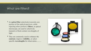
4. What are Filters?
 An optical filter selectively transmits one
portion of the optical spectrum, while
rejecting other portions. Filters, in optical
microscope, are used to selectively
transmit or block certain wavelengths of
light.
 They are commonly used to enhance the
contrast, improve visibility, or select
specific wavelengths for observation..........
5. What are Filters?
 They are designed to manipulate light in various ways, allowing us to control
the intensity, color, and polarization .
 The light source will emit light of all seven colors- violet, indigo, blue, green,
yellow, orange and red. Every color will produce an image of different
temperature, contrast, & brightness.
 Optical filters are frequently used to isolate specific wavelengths of light for data
collection and analysis, for example in fluorescence microscopy.
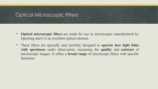
6. Optical Microscopic Filters
• Optical microscopic filters are made for use in microscopes manufactured by
Optolong and it is an excellent optical element.
• These filters are specially and carefully designed to operate how light links
with specimens under observation, increasing the quality and contrast of
microscopic images. It offers a broad range of microscope filters with specific
functions.
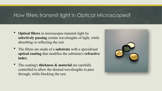
8. How filters transmit light in Optical Microscopes?
 Optical filters in microscopes transmit light by
selectively passing certain wavelengths of light, while
absorbing or reflecting the rest.
 The filters are made of a substrate with a specialized
optical coating that modifies the substrate's refractive
index.
 The coating's thickness & material are carefully
controlled to allow the desired wavelengths to pass
through, while blocking the rest.
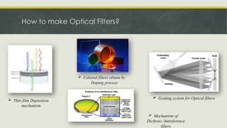
9. How to make Optical Filters?
 Here are some methods for the formation of optical filters:
â–¡ Thin Film Deposition method: In this technique multiple layers of different material are deposited on the
substrate by using techniques like physical vapor deposition (PVD) or chemical vapor deposition (CVD).This
is done to transmit or reflect specific wavelength of light by controlling thickness and composition of
material. This method is often used to create band pass-, long pass-, short pass-, & notch- filters.
â–¡ Photolithography: This technique involves using photoresist materials and light patterning to create
intricate patterns on a substrate. By selectively etching or depositing materials onto the substrate following
the pattern, optical filters with precise geometries and properties can be fabricated. This technique is mostly
used in semiconductor industries.
â–¡ Dichroic Coating: This technique involves coating of thin layers of materials with different refractive
indices on substrate. These layers selectively transmit or reflect light based on its polarization or wavelength.
The filters obtain from this technique are used in applications such as microscopy, photography, and stage
lighting………….
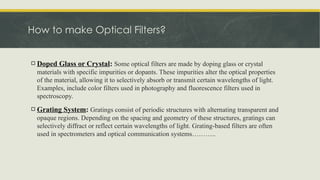
10. How to make Optical Filters?
â–¡ Doped Glass or Crystal: Some optical filters are made by doping glass or crystal
materials with specific impurities or dopants. These impurities alter the optical properties
of the material, allowing it to selectively absorb or transmit certain wavelengths of light.
Examples, include color filters used in photography and fluorescence filters used in
spectroscopy.
â–¡ Grating System: Gratings consist of periodic structures with alternating transparent and
opaque regions. Depending on the spacing and geometry of these structures, gratings can
selectively diffract or reflect certain wavelengths of light. Grating-based filters are often
used in spectrometers and optical communication systems………..
11. How to make Optical Filters?
 Thin film Deposition
mechanism
 Colored filters obtain by
Doping process
 Grating system for Optical filters
 Mechanism of
Dichroic /Interference
filters
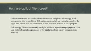
12. How are optical filters used?
 Microscope filters are used for both observation and photo microscopy. Each
microscope filter is used for a different purpose and all are typically placed in the
light path, either over the illuminator or in a filter slot that lies in the light path.
 Microscopy filters act to modify the light within an optical imaging system. This
can be for observation purposes or for capturing high-quality images using a
detector.
13. How do Optical filter work?
(Main types of Optical filters)
Absorptive
filters
Interference
filters
14. How do optical filters work or use?
 Absorptive filters absorb certain
wavelengths of light and transmit others.
They are made from coloured glass or
synthetic coloured gels that absorb the
undesired wavelengths of light.
 Optical interference filters employ the
interference of light waves to selectively transmit
or reflect certain wavelengths of light. The filter is
coated with dozens to hundreds of thin layers of
material with different refractive indices. The
thicknesses of the layers are carefully controlled
so that the desired wavelengths of light interfere
constructively and are transmitted, while
undesired wavelengths interfere destructively and
are reflected, or blocked. Sem-rock specializes in
innovating, designing, and producing high-
performance thin film optical interference filters.
Use of a specific type of optical filter depends on the
application. For example, a band pass filter might be
used to measure only the intensity of a specific
colour in an image of a living cell, while a notch filter
might be used to remove unwanted noise from a
medical image.
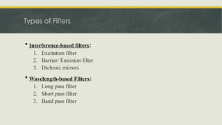
15. Types of Filters
 Interference-based filters:
1. Excitation filter
2. Barrier/ Emission filter
3. Dichroic mirrors
 Wavelength-based Filters:
1. Long pass filter
2. Short pass filter
3. Band pass filter
16. Interference-based Filters
 The 3 most common types of filters used for color selection in fluorescence
microscopy are excitation filters, barrier filters and dichroic beam splitters. In
modern microscopes, these are typically interference-based filters.
1. Excitation filters permit the passage of specific wavelengths of light
(excitation wavelengths) on the way towards the specimen. Excitation
filters include blue glass (BG) or ultraviolet glass (UG).
2. Barrier/emission filters attenuate the excitation wavelengths and
permit only the selected emission wavelengths to pass towards the eye
or the detector. Emission/barrier filters include yellow glass (Y or GG)
or red glass (R or RG).
3. Dichroic mirrors are specialized filters that consist of a thin piece of
coated material (often UV-grade fused silica) set at a 45° angle. This
coated material is designed to efficiently reflect the excitation
wavelengths and transmit the emission wavelengths with efficiencies of
up to 95%.
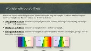
17. Wavelength-based filters
Filters can also normally only pass either short wavelengths, long wavelengths, or a band between long and
short wavelengths and these are termed and defined as follows:
 Long pass (LP) filters transmit wavelengths greater than a certain wavelength, described by wavelength
at 50% of peak transmission.
 Short pass (SP) filters transmit wavelengths below a certain wavelength.
 Band pass (BP) filters transmit wavelengths of light between two different wavelengths, giving a band of
transmitted wavelengths.
18. Other types of filters……
 Neutral-density (ND) filters: It is used to reduce the intensity of illumination light across a broad spectrum,
without modifying the range of wavelengths available. They have constant attenuation across a range of visible
wavelengths, and thus specifically reduce light intensity through reflecting or absorption. ND filters are
available in multiple densities and materials and can be stacked to increase optical density and increasingly
attenuate light intensity.
 Wedge filters: The thickness changes continuously, or in steps through the filter in the shape of a wedge.
These are also known as linearly variable filters (LVF). It is used for applications such as hyper spectral sensors.
 Polarizing filters: These filters polarize light either linearly or circularly. This can be used for polarized light
microscopy, which a label-free method to examine bire-fringent (double refracting) anisotropic materials.
 Infrared (IR or heat) filters: The filters either selectively block or transmit IR light. Many IR filters are
used to prevent unwanted heating due to IR light. Illuminator lamp houses often incorporate an infrared light
suppression filter. Near-infrared (NIR) imaging is powerful because tissue transmission is higher at longer
wavelengths, ideal for applications such as small animal imaging. NIR filter sets are available for this type of
imaging……
19. Other Types of filters
 Ultraviolet (UV) filters: The filters either selectively block or transmit UV light. Making filters
for the UV region of the electromagnetic spectrum is difficult, but new coatings using ion beam
sputter technology using newly developed coatings now offer filters for the 250–320 nm range.
 Didymium filters: These filters are made of didymium glass to increase the intensity and saturation
of red objects. This helps to prevent the washed-out problem that some colored stains give. They are
often used with histopathological staining to enhance dyes such as eosin, fuchsin, and methylene
blue.
 Yellow filters: These filters fine-tune the color balance of tungsten and halogen microscope light
sources for color photomicrography. The yellow filter can also be helpful
for metallurgical microscopy applications to identify failings in metal structures.
 Ground glass filters: These filters are placed over an illuminator to give a more even and diffused
light. These are often used with tungsten light sources.
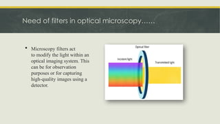
20. Need of filters in optical microscopy……
 Microscopy filters act
to modify the light within an
optical imaging system. This
can be for observation
purposes or for capturing
high-quality images using a
detector.
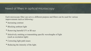
21. Each microscopy filter can serve a different purpose and filters can be used for various
improvements such as following :
 Increasing contrast
 Blocking ambient light
 Removing harmful UV or IR rays
 Selectively omitting or transmitting specific wavelengths of light
(such as excitation light)
 Correcting light path issues
 Reducing the intensity of the light.
Need of filters in optical microscopy
22. Applications of optical filters
Optical filters are used in a wide variety of applications, including;
 Fluorescence microscopy: Fluorescence allows us to distinguish
different types of tissues with colors, and microscopy allows you
to magnify the image so that you can see the detail that you need.
 Medical testing and imaging: A wide range of optical devices are
used for PCR testing (e.g. COVID-19 tests), cancer screening,
DNA sequencing, wearable medical sensors, and many other
purposes. Optical filters are key components that enable the
correct functioning of these devices.
 Optical spectroscopy: Scientists can identify the chemical
composition of materials using optical spectrometers, in which
optical filters isolate specific wavelengths of light for analysis.
 Industrial applications: Optical filters are used in industrial
applications, such as machine vision and quality control, to detect
defects in products or to identify object
L
a
s
e
r
S
p
e
c
t
r
o
m
e
t
e
r
Laser-line
Band pass
filter
Objec
t
Raman Long
pass edge
filter
23. Disadvantages
Disadvantages of the two most common types of optical filters are:
1)Absorptive Filters:
 Poor Long-Term Temperature Resistance: Absorptive filters may not maintain their
performance over extended periods under varying temperatures.
 Inadequate Precision: They are less precise compared to other filter types, making them less
suitable for precision applications.
2)Dichroic (Interference) Filters:
 Higher Cost : Dichroic filters are more delicate and expensive due to their precise construction
using thin film technology.
24. Conclusion
 Optical filters, in summary, are essential for improving the power of optical microscopy and allowing experts to
precisely and precisely control light wavelengths. Filters provide a multitude of applications such as fluorescence
imaging, spectrum analysis, and contrast enhancement by selectively transmitting or blocking particular light
wavelengths. Several techniques, including photolithography, dichroic coating, and thin film deposition, are used to
create optical filters; each has unique benefits and uses.
 The variety of filter types- such as polarizing and infrared filters, interference filters, and absorptive filters-
emphasizes how adaptable they are to meeting various microscopy needs and difficulties. Dichroic filters may be
more expensive because of their complex construction, whilst absorptive filters might have limits with regard to
precision and long-term temperature resistance. However, both kinds provide substantial contributions to the
advancement of scientific inquiry, healthcare diagnosis, industrial quality assurance, and other domains that depend
on optical imaging technology.
 Further advancements in microscopy performance are anticipated as technology develops, thanks to the creativity
and enhancement of optical filters, which will allow for increased accuracy, effectiveness, and adaptability in a
variety of applications. Researchers and practitioners can fully utilize optical filters to unlock new insights and
discoveries in a variety of scientific and industrial sectors by knowing their principles and capabilities.