final stuff
âĒDownload as PPTX, PDFâĒ
0 likesâĒ177 views

The document describes a project to implement multiplayer ping pong on a VGA display using VHDL. It was done by a student at Thapar University under the guidance of a project engineer. The project involved developing VHDL code to simulate the classic pong game on an FPGA board with a VGA connector. It describes generating the video signals, designing the paddles and ball to move and bounce, and a lab setup with additional game ideas like Breakout.


final stuff
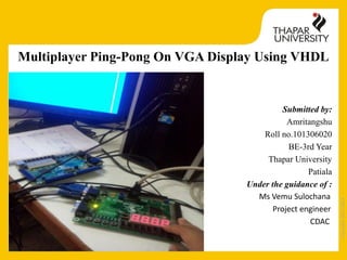
- 1. Copyright2013-2014 Multiplayer Ping-Pong On VGA Display Using VHDL Submitted by: Amritangshu Roll no.101306020 BE-3rd Year Thapar University Patiala Under the guidance of : Ms Vemu Sulochana Project engineer CDAC
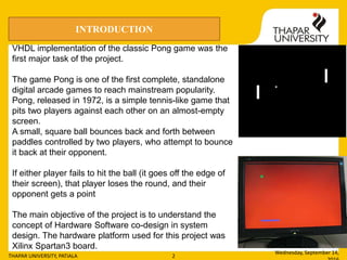
- 2. Copyright2013-2014 Wednesday, September 14, THAPAR UNIVERSITY, PATIALA 2 VHDL implementation of the classic Pong game was the first major task of the project. The game Pong is one of the first complete, standalone digital arcade games to reach mainstream popularity. Pong, released in 1972, is a simple tennis-like game that pits two players against each other on an almost-empty screen. A small, square ball bounces back and forth between paddles controlled by two players, who attempt to bounce it back at their opponent. If either player fails to hit the ball (it goes off the edge of their screen), that player loses the round, and their opponent gets a point The main objective of the project is to understand the concept of Hardware Software co-design in system design. The hardware platform used for this project was Xilinx Spartan3 board. INTRODUCTION
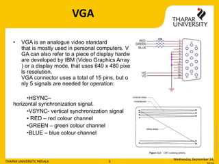
- 3. Copyright2013-2014 VGA âĒ VGA is an analogue video standard that is mostly used in personal computers. V GA can also refer to a piece of display hardw are developed by IBM (Video Graphics Array ) or a display mode, that uses 640 x 480 pixe ls resolution. VGA connector uses a total of 15 pins, but o nly 5 signals are needed for operation: âĒHSYNCâ horizontal synchronization signal. âĒVSYNC- vertical synchronization signal âĒ RED â red colour channel âĒGREEN â green colour channel âĒBLUE â blue colour channel Wednesday, September 14, THAPAR UNIVERSITY, PATIALA 3
- 4. Copyright2013-2014 Components of the program Wednesday, September 14, THAPAR UNIVERSITY, PATIALA 4 Main Contains all the components and their definitions Sync module Generates h sync and v sync signals Pixel generation module Generates rgb signal
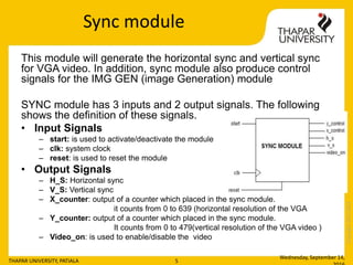
- 5. Copyright2013-2014 Sync module This module will generate the horizontal sync and vertical sync for VGA video. In addition, sync module also produce control signals for the IMG GEN (image Generation) module SYNC module has 3 inputs and 2 output signals. The following shows the definition of these signals. âĒ Input Signals â start: is used to activate/deactivate the module â clk: system clock â reset: is used to reset the module âĒ Output Signals â H_S: Horizontal sync â V_S: Vertical sync â X_counter: output of a counter which placed in the sync module. it counts from 0 to 639 (horizontal resolution of the VGA â Y_counter: output of a counter which placed in the sync module. It counts from 0 to 479(vertical resolution of the VGA video ) â Video_on: is used to enable/disable the video Wednesday, September 14, THAPAR UNIVERSITY, PATIALA 5
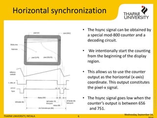
- 6. Copyright2013-2014 Horizontal synchronization Wednesday, September 14, THAPAR UNIVERSITY, PATIALA 6 âĒ The hsync signal can be obtained by a special mod-800 counter and a decoding circuit. âĒ We intentionally start the counting from the beginning of the display region. âĒ This allows us to use the counter output as the horizontal (x-axis) coordinate. This output constitutes the pixel-x signal. âĒ The hsync signal goes low when the counterâs output is between 656 and 751.
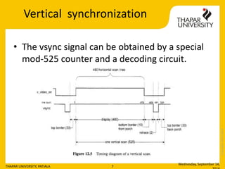
- 7. Copyright2013-2014 Vertical synchronization âĒ The vsync signal can be obtained by a special mod-525 counter and a decoding circuit. Wednesday, September 14, THAPAR UNIVERSITY, PATIALA 7
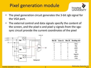
- 8. Copyright2013-2014 Pixel generation module âĒ The pixel generation circuit generates the 3-bit rgb signal for the VGA port. âĒ The external control and data signals specify the content of the screen, and the pixel-x and pixel-y signals from the vga- sync circuit provide the current coordinates of the pixel Wednesday, September 14, THAPAR UNIVERSITY, PATIALA 8
- 9. Copyright2013-2014 Design of the Paddle âĒ Each paddle has a fixed X-coordinate on the screen, and the only thing that will change is the Y-coordinate as the user moves the paddle up and down. âĒ The paddle module will take two one-bit inputs: âUâ, telling the paddle to move up, and âDâ, to move down. âĒ If the U input is 1, the paddle will move up by 4 (decrease Y by 4). âĒ If the D input is â1â, the paddle will move down by 4 (increase Y by 4). âĒ If both are â1â, the paddle should stay in position. Wednesday, September 14, THAPAR UNIVERSITY, PATIALA 9
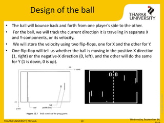
- 10. Copyright2013-2014 Design of the ball âĒ The ball will bounce back and forth from one playerâs side to the other. âĒ For the ball, we will track the current direction it is traveling in separate X and Y-components, or its velocity. âĒ We will store the velocity using two flip-flops, one for X and the other for Y. âĒ One flip-flop will tell us whether the ball is moving in the positive-X direction (1, right) or the negative-X direction (0, left), and the other will do the same for Y (1 is down, 0 is up). Wednesday, September 14, THAPAR UNIVERSITY, PATIALA 10
- 11. Copyright2013-2014 Ball collisions âĒ When the ball collides with a paddle or the border of the screen, the ball will bounce away from the object it collides with. This will be done by reversing direction away from the collision. Wednesday, September 14, THAPAR UNIVERSITY, PATIALA 11
- 12. Copyright2013-2014 Animation of the ball âĒ When an object changes its location gradually in each scan, it creates the illusion of motion and becomes animated. âĒ To achieve this, we can use registers to store the boundaries of an object and update its value in each scan. âĒ In the pong game, the paddle is controlled by two pushbuttons and can move up and down, and the ball can move and bounce in all directions. Wednesday, September 14, THAPAR UNIVERSITY, PATIALA 12
- 13. Copyright2013-2014 Implimentation Wednesday, September 14, THAPAR UNIVERSITY, PATIALA 13
- 14. Copyright2013-2014 Lab setup Wednesday, September 14, THAPAR UNIVERSITY, PATIALA 14
- 15. Copyright2013-2014 Wednesday, September 14, THAPAR UNIVERSITY, PATIALA 15 Actual lab setup used
- 16. Copyright2013-2014 Additional projects âĒ Breakout game The breakout game is a somewhat like the pong game. In this game, the left wall is replaced by several layers of âbricks.â When the ball hits a brick, the ball bounces back and the brick disappears. Wednesday, September 14, THAPAR UNIVERSITY, PATIALA 16
- 17. Copyright2013-2014 Background colour options âĒ Colour multiplexing circuit âĒ This provides 9 colour options in multiplayer ping pong to change the background of the screen through switches on the spartan 3. Wednesday, September 14, THAPAR UNIVERSITY, PATIALA 17
- 18. Copyright2013-2014 FSM based vending machine Wednesday, September 14, THAPAR UNIVERSITY, PATIALA 18
- 19. Copyright2013-2014 âĒ INTRODUCTION Vending Machines are used to dispense various products like Coffee, Snacks, and Cold Drink etc. when money is inserted into it. âĒ Vending Machines have been in existence since 1880s. The first commercial coin operated machine was introduced in London and England used for selling post cards. âĒ The vending machines are more accessible and practical than the convention purchasing method
- 20. Copyright2013-2014 Wednesday, September 14, THAPAR UNIVERSITY, PATIALA 20
- 21. Copyright2013-2014 Case1 : snacks selected
- 22. Copyright2013-2014 Case2 : cofee selected
- 23. Copyright2013-2014 Case3 : cold drinks selected
- 24. Copyright2013-2014 Case4 : candy selected
- 25. Copyright2013-2014 Case5 : purchase cancel