Final Year Project Presentation
- 3. Applications Remote Data Acquisition Rescue Operation Indoor and Outdoor Flight Surveillance
- 4. Modeling Mechanical Design Sensors and Actuators Signal Conditioning Control Strategy
- 5. An aircraft that is lifted and propelled by four propellers. Control and maneuvering is achieved by varying the relative speeds of the four rotors. Vertical Take Off and Landing
- 7.  PRO-E simulation was used to determine:  Dimensions of the craft (0.25 m).  Total mass (1.5 kg) of the PVC structure  Moment of inertia (0.025 kg.m2) .  Propeller size (9 inch).  The results obtained enabled us to select a suitable BLDC motor for the quad rotor.
- 8.  9 Degrees of Freedom - Razor IMU ( Sparkfun.com)  Specifications of IMU.  LY530ALH (300°/s single-axis gyro),  LPR530ALH (300°/s dual-axis gyro),  ADXL345 (three-axis accelerometer),  HMC5843 (three-axis magnetometer)
- 9.  BLDC motor - out runner (the outer shell spins) is used  Specifications:  Weight: 56g  Voltage: 10V  KV: 1200 RPM/V  Max Efficiency Current: 15.5A  Max Power out: 180W.  An electronic speed controller (ESC) is used to control the speed of electric motors.  It is a pulse-width modulation (PWM) controller Turnigy Bell 2409-18T
- 10.  Two 2200mAh 3S 25C Lipo Packs and a separate battery used for electronic circuitry.  Size: 9 x 5  Clockwise and Counter-Clockwise orientation.
- 11.  dsPIC 30f5015 motor control series microcontroller for onboard computation.  All calculations were done in fixed point (signed Q15.16)  Capable of providing 4 simultaneous independent PWM’s  dsPIC features, hardware multiplier, 16 bit architecture  Operating with a clock multiplier to obtain 14MIPS.
- 13.  IMU data is corrupted and has to be filtered to make it usable.  Gyro integration gives orientation but drifts over time.
- 14.  Accelerometer gives the gravity vector.  Integration of rate gyros gives attitude.  Noise in gyros:  Offset  White noise  Leads to drift  The ‘g’ reference vector from the accelerometer is used to correct this drift
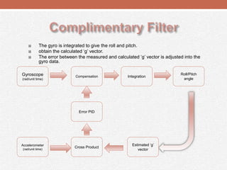
- 15.  The gyro is integrated to give the roll and pitch.  obtain the calculated ‘g’ vector.  The error between the measured and calculated ‘g’ vector is adjusted into the gyro data. Gyroscope (rad/unit time) Compensation Roll/Pitch angle Accelerometer (rad/unit time) Error PID Cross Product Integration Estimated ‘g’ vector
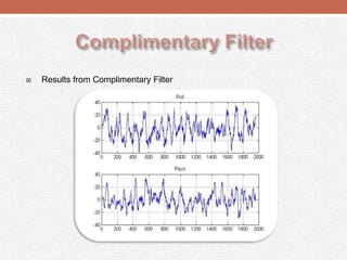
- 16.  Results from Complimentary Filter
- 17.  Two options for orientation estimation  The Complimentary Filter:  does not require the system model  is optimized for microcontroller implementation  performance is comparable to the Kalman Filter Kalman filter Complimentary filter
- 18.  PID controller was used for roll and pitch control.  Larger P leads to faster response,  I used for reference tracking  D dampens the oscillations, reduces overshoot  A simulation was done using the mathematical model in MATLAB.  The gains found were fine tuned on the actual system
- 19.  Objective:  Sensing translation in X- axis  Sensing translation in Y- axis  Yaw computation
- 20.  Wireless camera over IP are very expensive.  Camera of the smart phone was used for live streaming.  Bluetooth link was used between the camera and the base station.  A Red Cross of the ground was used as reference for determining the position of the craft.
- 21. Image Acquistion Image Segmentation Blob Detection Blob Filtering & Analysis Centroid & Yaw Evaluation Error Computation
- 32. Translation control Wireless communication Ultra sonic sensor for object avoidance
- 35. Q & A Thank You !


