Fire dampers installation
- 1. FIRE DAMPER INSTALLATION Mohammed Mukaram Jah, Mechanical Engineer mukarram169@rediffmail.com +91 9701 99 3862 1
- 2. CONTENTS ï FIRE DAMPER AND ITS SIGNIFICANCE ï FIRE RESISTANCE RATING ï WHERE FIRE DAMPERS ARE REQUIRED ï APPROVED INSTALLATION ï IMPROPER INSTALLATION 2
- 3. Fire Damper and its Significance Fire Damper is a device installed in an air distribution system, designed to close automatically upon detection of heat to interrupt migratory airflow and to restrict the passage of flame(NFPA 90A). This is accomplished only when these dampers are installed in accordance with SMACNA Fire, Smoke and Radiation Dampers Installation Guide. Fire Resistance The time in minutes and Hours, that materials or assemblies have withstood a fire exposure as established in accordance with the test procedures of NFPA 251, Standards Methods of tests of fire Endurance of building construction and Materials(NFPA 90A). Where Fire Dampers are Required ?? âĒ Fire Dampers are required wherever fire resistance integrity of the wall is to be maintained. âĒ Required wherever there is duct penetration either through fire rated wall or fire rated roof. 3
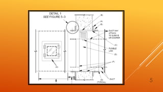
- 4. APPROVED INSTALLATION: Fire and Smoke dampers shall be manufactured and installed as per the latest issue of SMACNA â Fire, Smoke and Radiation dampers installation guide.â As per SMACNA below are the important items to be considered for installation. A. Retaining Angle B. Expansion Space C. Damper Sleeve D. Fire Damper E. Retaining Angle fastened to sleeve F. Damper attachment to sleeve G. Connection to Duct Below is the picture depicting above items in the installation of fire damper. 4
- 5. 5
- 6. 6 A. Retaining Angle : âĒ Retaining Angles shall be secured to sleeve on 8â centers and shall not be fixed to walls. âĒ Retaining angles shall overlap the structure opening 1â minimum and cover corner opening. âĒ Retaining angle shall be minimum of 1Â―â x 1Â―â x 16 gauge(40 x 40 x 1.6mm). However some manufacturers may allow lower gauge for small size and may require heavier gauge for larger ducts. B. Expansion Space : âĒ The annular space/clearance between fire damper sleeve and wall/roof opening is termed as expansion space. âĒ This clearance shall be minimum 1/8â per linear foot(10mm per liner meter) of width and height unless otherwise stated in the listing of the assembly. âĒ Sleeve may rest on the bottom of the opening and need not be centered(SMACNA)
- 7. 7 C. Damper Sleeve : By UL 555, ducts are to be terminated at fire damper sleeves or damper frames. Sleeve thickness depends on the type of connection as per below table. . Sleeves may be omitted on certain alternative damper arrangements that are in compliance with UL 555, Standard for Fire Dampers. The damper manufacturers Installations and Operating Instructions shall state whether sleeves may be omitted
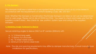
- 8. 8 D. Fire Damper : Fire dampers shall bear a label from a recognized testing laboratory (such as UL) or be tested in accordance with the requirements of Uniform Building Code, UBC STD 43-7. Note: Whether Fire Damper or Combination Fire/Smoke Damper is UL listed or not can be determined from UL web page. Please visit UL site at WWW.UL.COM. You need to check and make sure that the supplied model is listed. Also check for size, position, System type and rating of the supplied dampers. E. Retaining Angle Fastened to Sleeve Secure retaining angles to sleeve ONLY on 8â centers (203mm) with a. Â― â(12mm) long weld b. žâ(6mm) nut and bolts c. No. 10 sheet metal screws d. Minimum 3/16â(5mm) steel rivets Note : The size and spacing requirements may differ by damper manufacturer. Consult manufacturer installations for specifications.
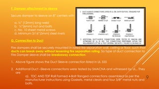
- 9. 9 F. Damper attachment to sleeve Secure damper to sleeve on 8â centers with a. Â―â (12mm) long weld b. žâ(6mm) nut and bolts c. No. 10 sheet metal screws d. Minimum 3/16â(5mm) steel rivets G. Connection to Duct Fire dampers shall be securely mounted in rated fire separation wall, ceiling or floor, such that ducts can break away without lessening fire separation rating. So type of duct connection to Fire Damper sleeve shall be breakaway connection. 1. Above figure shows the Duct Sleeve connection listed in UL 555 2. Additional Duct âSleeve connections were tested by SMACNA and witnessed by UL.. They are a). TDC AND TDF Roll Formed 4-Bolt flanged connections assembled as per the manufacturer instructions using Gaskets, metal cleats and four 3/8â metal nuts and bolts.
- 10. 10 b). Manufactured slip on 4-Bolt flanged connections assembled as per manufacturer instructions using Gaskets and Plastic Cleats. H. Access Door : Install access door shall be installed as shown in figure. Access doors shall be maximum of 24âx24â and a minimum of 6âx 6â(SMACNA). Access doors (points) shall be identified by a label with letters not less than Â―â (13 mm) in height reading FIRE DAMPER (UMC Para 605.5).
- 11. 11 IMPROPER INSTALLATION Figure below shows two main improper installations encountered as per SMACNA.
- 12. 12 Item 1: Sealing of the fire damper retaining angles is not a requirement of an approved damper installation If the local authority having jurisdiction mandates that the angles be sealed, contractors should issue a Request For Information (RFI) to design professionals such that the proper approved sealants be used. In no case should the retaining angles be sealed with any product not approved by the damper manufacturer including Through Penetration Fire stop products. Using unapproved products could be a violation of the damper manufacturerâs conditions of test and listing, could void the UL listing of the damper and could render the damper inoperable Item 2: Introduction of any materials including mineral wool, ceramic fiber or sealants of any kind into the required expansion space between the damper sleeve and fire partition has not been tested, has not been approved, and is not permitted by damper manufacturers. Doing so could be a violation of the manufacturerâs conditions of test and listing, could void the UL listing of the damper and could render the damper inoperable. Indiscriminate and unnecessary deviations from standard fire damper installations should be avoided. Unless a deviation is specifically approved by the damper manufacturer, it could compromise the function for which the damper was ultimately installed.
- 13. 13 Below is the pictures showing improper installation in one project.
- 14. 14 VERTICAL FIRE DAMPER INSTALLATION
- 15. 15 HORIZONTAL FIRE DAMPER INSTALLATION
- 16. 16 THANK YOU


