際際滷

際際滷Share a Scribd company logo
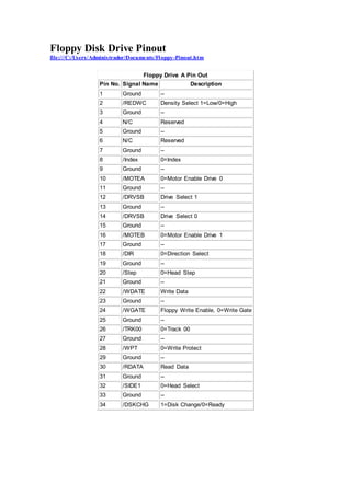
3.5 inch micro Floppy Disk Drive micro connector (26x1 pin) pinout 
http://pinoutsguide.com/Storage/26pin_microfloppy_pinout.shtml 
Be careful! The conductor side at the flexfoil connector can vary. 
Pin 
Pin 
Name 
Description 
1 VCC VCC +5V 
2 /INDEX Index 
3 VCC VCC +5V 
4 /DRVS Drive Sel 
5 VCC VCC +5V 
6 /DSKCHG Disk Change 
7 RES Reserved 
8 READY 
used only in older drives. 
In newer drives N/C. 
9 MEDIA 
used only in older drives. 
In newer drives N/C. 
10 /MOTE Motor Enable 
11 /REDWC Density Select 
12 /DIR Direction 
13 RES Reserved (Inuse) 
14 /STEP Step 
15 GND Ground 
16 /WDATE Write Data 
17 GND Ground 
18 /WGATE Write Gate 
19 GND Ground 
20 /TRK00 Track00 
21 GND Ground 
22 /WPT Write Protect 
23 GND Ground 
24 /RDATA Read Data 
25 GND Ground 
26 /SIDE1 Side 1 Select
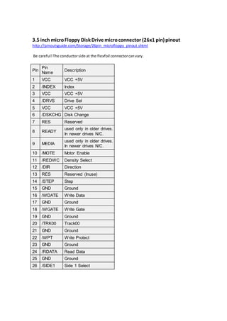
Floppy Disk Drive Pinout 
file:///C:/Users/Administrador/Documents/Floppy-Pinout.htm 
Floppy Drive A Pin Out 
Pin No. Signal Name Description 
1 Ground -- 
2 /REDWC Density Select 1=Low/0=High 
3 Ground -- 
4 N/C Reserved 
5 Ground -- 
6 N/C Reserved 
7 Ground -- 
8 /Index 0=Index 
9 Ground -- 
10 /MOTEA 0=Motor Enable Drive 0 
11 Ground -- 
12 /DRVSB Drive Select 1 
13 Ground -- 
14 /DRVSB Drive Select 0 
15 Ground -- 
16 /MOTEB 0=Motor Enable Drive 1 
17 Ground -- 
18 /DIR 0=Direction Select 
19 Ground -- 
20 /Step 0=Head Step 
21 Ground -- 
22 /WDATE Write Data 
23 Ground -- 
24 /WGATE Floppy Write Enable, 0=Write Gate 
25 Ground -- 
26 /TRK00 0=Track 00 
27 Ground -- 
28 /WPT 0=Write Protect 
29 Ground -- 
30 /RDATA Read Data 
31 Ground -- 
32 /SIDE1 0=Head Select 
33 Ground -- 
34 /DSKCHG 1=Disk Change/0=Ready
More Related Content

Floppy micro conector

  • 1. 3.5 inch micro Floppy Disk Drive micro connector (26x1 pin) pinout http://pinoutsguide.com/Storage/26pin_microfloppy_pinout.shtml Be careful! The conductor side at the flexfoil connector can vary. Pin Pin Name Description 1 VCC VCC +5V 2 /INDEX Index 3 VCC VCC +5V 4 /DRVS Drive Sel 5 VCC VCC +5V 6 /DSKCHG Disk Change 7 RES Reserved 8 READY used only in older drives. In newer drives N/C. 9 MEDIA used only in older drives. In newer drives N/C. 10 /MOTE Motor Enable 11 /REDWC Density Select 12 /DIR Direction 13 RES Reserved (Inuse) 14 /STEP Step 15 GND Ground 16 /WDATE Write Data 17 GND Ground 18 /WGATE Write Gate 19 GND Ground 20 /TRK00 Track00 21 GND Ground 22 /WPT Write Protect 23 GND Ground 24 /RDATA Read Data 25 GND Ground 26 /SIDE1 Side 1 Select
  • 2. Floppy Disk Drive Pinout file:///C:/Users/Administrador/Documents/Floppy-Pinout.htm Floppy Drive A Pin Out Pin No. Signal Name Description 1 Ground -- 2 /REDWC Density Select 1=Low/0=High 3 Ground -- 4 N/C Reserved 5 Ground -- 6 N/C Reserved 7 Ground -- 8 /Index 0=Index 9 Ground -- 10 /MOTEA 0=Motor Enable Drive 0 11 Ground -- 12 /DRVSB Drive Select 1 13 Ground -- 14 /DRVSB Drive Select 0 15 Ground -- 16 /MOTEB 0=Motor Enable Drive 1 17 Ground -- 18 /DIR 0=Direction Select 19 Ground -- 20 /Step 0=Head Step 21 Ground -- 22 /WDATE Write Data 23 Ground -- 24 /WGATE Floppy Write Enable, 0=Write Gate 25 Ground -- 26 /TRK00 0=Track 00 27 Ground -- 28 /WPT 0=Write Protect 29 Ground -- 30 /RDATA Read Data 31 Ground -- 32 /SIDE1 0=Head Select 33 Ground -- 34 /DSKCHG 1=Disk Change/0=Ready