Flow controll valve
- 1. The purpose of flow control in a hydraulic system is to regulate speed. All the devices discussed here control the speed of an actuator by regulating the flow rate. Flow rate also determines rate of energy transfer at any given pressure. The two are related in that the actuator force multiplied by the distance through which it moves (stroke) equals the work done on the load. The energy transferred must also equal the work done. Actuator speed determines the rate of energy transfer (i.e., horsepower), and speed is thus a function of flow rate. Directional control, on the other hand, does not deal primarily with energy control, but rather with directing the energy transfer system to the proper place in the system at the proper time. Directional control valves can be thought of as fluid switches that make the desired "contacts." That is, they direct the high-energy input stream to the actuator inlet and provide a return path for the lower-energy oil. It is of little consequence to control the energy transfer of the system through pressure and flow controls if the flow stream does not arrive at the right place at the right time. Thus, a secondary function of directional control devices might be defined as the timing of cycle events. Because fluid flow often can be throttled in directional-control valves, some measure of flow rate or pressure control can also be achieved with them. Different types of flow measurement Controlling flow of a fluid-power system does not necessarily mean regulating volume per unit of time from a valve. Flow rate can be specified three different ways, so it is important to be aware of how flow is to be specified or measured: Volumetric flow rate, Qv, expressed in units of in.3/sec or min - or cc/sec or cc/min in SI metric measure - is used to calculate the linear speeds of piston rods or rotational speeds of motor shafts. Weight flow rate, Qw, expressed in units of lb/sec or lb/min, is used to calculate power using English units of measure. Mass flow rate, Qg, expressed in units of slugs/sec or slugs/min for English measure - or kg/sec or kg/min in SI metric measure - is used to calculate inertia forces during periods of acceleration and deceleration.
- 2. Because they control the quantity of fluid that flows through the valve per unit of time, the same control valves are used for all three types of flow rates. Control of flow rate with valves Fig. 1. Simple fixed orifice (a) and variable orifice (b) flow controls. There are eight types of flow-control valves: Orifices - A simple orifice in the line, Figure 1(a), is the most elementary method for controlling flow. (Note that this is also a basic pressure control device.) When used to control flow, the orifice is placed in series with the pump. An orifice can be a drilled hole in a fitting, in which case it is fixed; or it may be a calibrated needle valve, in which case it functions as a variable orifice, Figure 1(b). Both types are non-compensated flow-control devices.
- 3. Fig. 2. Flow regulator adjusts to variations in inlet and output press ures. Flow regulators - This device, Figure 2, which is slightly more sophisticated than a fixed orifice, consists of an orifice that senses flow rate as a pressure drop across the orifice; a compensating piston adjusts to variations in inlet and outlet pressures. This compensating ability provides closer control of flow rate under varying pressure conditions. Control accuracy may be 5%, possibly less with specially calibrated valves that operate around a given flow-rate point. Fig. 3. Bypass flow regulator returns excess flow from pump to tank. Bypass flow regulators - In this flow regulator, flow in excess of set flow rate returns to reservoir through a bypass port, Figure 3. Flow rate is controlled by throttling fluid across a
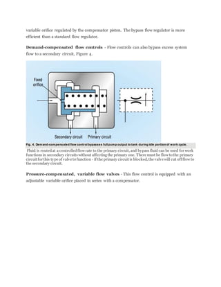
- 4. variable orifice regulated by the compensator piston. The bypass flow regulator is more efficient than a standard flow regulator. Demand-compensated flow controls - Flow controls can also bypass excess system flow to a secondary circuit, Figure 4. Fig. 4. Demand-compensated flow control bypasses full pump output to tank during idle portion of work cycle. Fluid is routedat a controlledflowrate to the primary circuit, and bypassfluid can be used for work functionsin secondary circuitswithout affectingthe primary one. There must be flow to the primary circuit for this type of valve to function - if the primary circuit is blocked, the valve will cut off flow to the secondary circuit. Pressure-compensated, variable flow valves - This flow control is equipped with an adjustable variable orifice placed in series with a compensator.
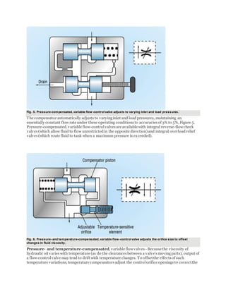
- 5. Fig. 5. Pressure-compensated, variable flow -control valve adjusts to varying inlet and load pressures. The compensator automatically adjusts to varyinginlet and load pressures, maintaining an essentially constant flow rate under these operating conditionsto accuraciesof 3% to 5%, Figure 5. Pressure-compensated, variable flow-controlvalvesare available with integral reverse-flowcheck valves(which allow fluid to flow unrestrictedin the opposite direction)and integral overloadrelief valves(which route fluid to tank when a maximum pressure is exceeded). Fig. 6. Pressure- and temperature-compensated, variable flow -control valve adjusts the orifice size to offset changes in fluid viscosity. Pressure- and temperature-compensated, variable flowvalves - Because the viscosity of hydraulic oil varieswith temperature (as do the clearancesbetween a valve'smovingparts), output of a flow-controlvalve may tend to drift with temperature changes. To offset the effectsof such temperature variations, temperature compensatorsadjust the controlorifice openings to correct the
- 6. effectsof viscosity changescausedby temperature fluctuationsof the fluid, Figure 6. Thisis done in combination with adjustments the controlorifice for pressure changes as well. Fig. 7. Priority valve supplies fluid at a set rate to a primary circuit. Priority valves - A priority valve, Figure 7, is essentially a flow-control valve that supplies fluid at a set flow rate to the primary circuit, thus functioning as a pressure-compensated flow-control valve. Flow in excess of that required by the primary circuit bypasses to a secondary circuit at a pressure somewhat below that of the primary circuit. Should inlet or load pressure (or both) vary, the primary circuit has priority over the secondary - as far as supplying the design flow rate is concerned.
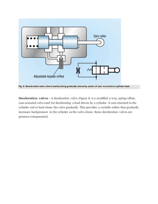
- 7. Fig. 8. Deceleration valve slows load by being gradually closed by action of cam mounted on cylinder load. Deceleration valves - A deceleration valve, Figure 8, is a modified 2-way, spring-offset, cam actuated valve used for decelerating a load driven by a cylinder. A cam attached to the cylinder rod or load closes the valve gradually. This provides a variable orifice that gradually increases backpressure in the cylinder as the valve closes. Some deceleration valves are pressure-compensated.


