ºÝºÝߣ

ºÝºÝߣShare a Scribd company logo
Flywheel Energy Storage System (FESS)
Today, flywheel energy storage systems are used for ride-through energy for a variety of
demanding applications surpassing chemical batteries.
A flywheel is essentially a mechanical battery consisting of a mass rotating around an axis.
It stores energy in the form of kinetic energy and works by accelerating a rotor to very high
speeds and maintaining the energy in the system as rotational energy.
Flywheel energy storage is a promising technology for replacing conventional lead acid
batteries as energy storage systems.
Most modern high-speed flywheel energy storage systems (FESS) consist of a huge rotating
cylinder supported on a stator (the stationary part of a rotary system) by magnetically
levitated bearings.
These bearings are permanent magnets which support the weight of the flywheel by repulsion
forces and are stabilised with electromagnets.
The theory and application
FESS utilise kinetic energy stored in a rotational mass with low frictional losses. The kinetic
energy of the system is described by the equation
Ek = ½ Iω2
where I is the moment of inertia and ω is the angular velocity of the rotating disc; when ω
or I increases, the energy of the system increases.
Once made of steel, flywheels are now made of a carbon fiber composite which has a high
tensile strength and can store much more energy. The amount of energy stored in the
flywheel is a function of the square of its rotational speed and its mass, so higher rotational
speeds are desirable. Spinning at the maximum possible speed results in an optimal energy-
to-mass ratio. However, the flywheel is then subject to significant centrifugal forces and
could be prone to failure at lower rotational speed than lower density materials.
FESS operate in a vacuum to reduce drag, friction and energy loss, and are connected to a
motor generator that interacts with the utility grid via advanced power electronics. They are
used in energy grid storage as a reserve for momentary grid frequency regulation and
balancing sudden changes between supply and consumption, so when short-term back up
power is required because the utility power fluctuates or is lost.
Electric energy input is used to accelerate the rotor up to speed using the built-in motor-
generator; the inertia allows the rotor to continue spinning and the resulting kinetic energy is
converted to electricity. Energy is discharged by drawing down kinetic energy using the same
motor as a generator.
But it is not a primary source of power generation. Extra power in the grid is shunted to the
flywheel and used to set them in motion. When the power is required later, the momentum of
the flywheel is used to generate power fed back to the grid.
Other applications
In the 1950s, flywheel energy storage systems were employed in vehicles such as gyrobuses
in Switzerland and Belgium and they could also replace conventional chemical batteries in
electric vehicles. They have also been utilized in rail transport, in aircraft launching systems
and by NASA in their G2 flywheel for spacecraft energy storage. They could also be used in
wind turbine to store energy during off-peak periods or during high wind speeds.
But that’s not all. Simple flywheels are found in friction toys, while more complex ones are
utilized in amusement rides such as rollercoasters, and in motorsports to improve
accelerations in cars.
Advantages
Compared to other means of storing electricity, FESS have long lifetimes and can go decades
with little to no maintenance. Flywheels found in the James Watt steam engine have been
working continuously for over 200 years.
FESS also has high specific energy and a large maximum power output. Their energy
efficiency – the ratio of energy out per energy in – can be as high as 90%.
Furthermore, such systems are not affected by temperature fluctuations like electric batteries
and are not subject to many other common failures. FESS is also less damaging to the
environment as they are composed of inert or benign materials.
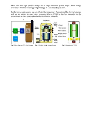
Fig. 1 Block diagram of Flywheel Storage Fig. 2 Flywheel Energy Storage System Fig. 3 Components of FESS

More Related Content

Flywheel Energy Storage.pdf

  • 1. Flywheel Energy Storage System (FESS) Today, flywheel energy storage systems are used for ride-through energy for a variety of demanding applications surpassing chemical batteries. A flywheel is essentially a mechanical battery consisting of a mass rotating around an axis. It stores energy in the form of kinetic energy and works by accelerating a rotor to very high speeds and maintaining the energy in the system as rotational energy. Flywheel energy storage is a promising technology for replacing conventional lead acid batteries as energy storage systems. Most modern high-speed flywheel energy storage systems (FESS) consist of a huge rotating cylinder supported on a stator (the stationary part of a rotary system) by magnetically levitated bearings. These bearings are permanent magnets which support the weight of the flywheel by repulsion forces and are stabilised with electromagnets. The theory and application FESS utilise kinetic energy stored in a rotational mass with low frictional losses. The kinetic energy of the system is described by the equation Ek = ½ Iω2 where I is the moment of inertia and ω is the angular velocity of the rotating disc; when ω or I increases, the energy of the system increases. Once made of steel, flywheels are now made of a carbon fiber composite which has a high tensile strength and can store much more energy. The amount of energy stored in the flywheel is a function of the square of its rotational speed and its mass, so higher rotational speeds are desirable. Spinning at the maximum possible speed results in an optimal energy- to-mass ratio. However, the flywheel is then subject to significant centrifugal forces and could be prone to failure at lower rotational speed than lower density materials. FESS operate in a vacuum to reduce drag, friction and energy loss, and are connected to a motor generator that interacts with the utility grid via advanced power electronics. They are used in energy grid storage as a reserve for momentary grid frequency regulation and balancing sudden changes between supply and consumption, so when short-term back up power is required because the utility power fluctuates or is lost. Electric energy input is used to accelerate the rotor up to speed using the built-in motor- generator; the inertia allows the rotor to continue spinning and the resulting kinetic energy is converted to electricity. Energy is discharged by drawing down kinetic energy using the same motor as a generator. But it is not a primary source of power generation. Extra power in the grid is shunted to the flywheel and used to set them in motion. When the power is required later, the momentum of the flywheel is used to generate power fed back to the grid. Other applications In the 1950s, flywheel energy storage systems were employed in vehicles such as gyrobuses in Switzerland and Belgium and they could also replace conventional chemical batteries in electric vehicles. They have also been utilized in rail transport, in aircraft launching systems and by NASA in their G2 flywheel for spacecraft energy storage. They could also be used in wind turbine to store energy during off-peak periods or during high wind speeds. But that’s not all. Simple flywheels are found in friction toys, while more complex ones are utilized in amusement rides such as rollercoasters, and in motorsports to improve accelerations in cars. Advantages Compared to other means of storing electricity, FESS have long lifetimes and can go decades with little to no maintenance. Flywheels found in the James Watt steam engine have been working continuously for over 200 years.
  • 2. FESS also has high specific energy and a large maximum power output. Their energy efficiency – the ratio of energy out per energy in – can be as high as 90%. Furthermore, such systems are not affected by temperature fluctuations like electric batteries and are not subject to many other common failures. FESS is also less damaging to the environment as they are composed of inert or benign materials. Fig. 1 Block diagram of Flywheel Storage Fig. 2 Flywheel Energy Storage System Fig. 3 Components of FESS