Gait and trajectory planning for legged robots
- 1. Gait and Trajectory Planning for Legged Robots -By Aishwary Singh Baghel
- 2. References ŌĆó Kyosuke Ono, Rongqiang Liu, 2012, ŌĆ£Optimal Biped Walking Locomotion Solved by TrajectoryŌĆØ. ŌĆó Kato, T., et al., 1981, ŌĆśŌĆśThe Realization of the Quasi Dynamic Walking by the Biped Walking Machine,ŌĆÖŌĆÖ Proc. of Int. Symp. on Theory and Practice and Manipulators, ROMANSY, pp. 341ŌĆō351. ŌĆó Miyazaki, F., and Arimoto, S., 1980, ŌĆśŌĆśA Control Theoretic Study on Dynamical Biped Locomotion,ŌĆÖŌĆÖ ASME J. Dyn. Syst., Meas., Control, 102~4!, pp. 233ŌĆō 239.
- 3. Gait Analysis ŌĆó Gait is the medical term to describe human locomotion or the way that we walk. ŌĆó It is a locomotion achieved through the movement of limbs. ŌĆó Different gait patterns are characterized by differences in limb movement patterns. ŌĆó Every individual has a unique gait pattern.
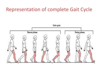
- 4. Phases of Gait Cycle
- 5. Stance Phase ŌĆó Heel strike (Initial Contact) ŌĆó Foot flat (Loading Response) ŌĆó Mid-stance (Mid Stance) ŌĆó Heel off (Terminal Stance) ŌĆó Toe off (Pre Swing)
- 7. Swing Phase ŌĆó 1) Acceleration (Initial Swing) ŌĆó 2) Mid-swing ŌĆó 3) Deceleration (Terminal Swing)
- 9. Representation of complete Gait Cycle
- 10. Trajectory Planning ŌĆó An optimal trajectory planning of walking legged robots ŌĆó Walking mechanism which has thighs, shanks and small feet. ŌĆó Mechanism is model to be a 3-degree-of-freedom link system composed of a stance leg and a 2-dof swing leg. ŌĆó The swing motion of 2-dof swing until knee collision. ŌĆó The swing motion of the straight leg until toe collision.
- 11. ŌĆó The control methods to generate a stable walking gait that have been proposed are a zero moment point. ŌĆó ZMP principle is commonly used because of its simplicity and clarity of the control strategy. ŌĆó The natural walking gait with minimum power consumption or minimum input can be calculated by the optimal trajectory planning method. ŌĆó The trajectory planning problem can be solved by the dynamic programing method.
- 13. ŌĆó Disregard the upper body because it has little effect on walking locomotion. ŌĆó Two legs are assumed to be directly connected to each other through an actuator. ŌĆó Both knee and ankle joints can be driven by individual actuators. ŌĆó Knee joint of the stance leg is passively locked by means of a stopper mechanism to prevent the mechanism from collapsing.
- 14. ŌĆó Ankle of the stance leg is modeled as a rotating joint fixed to the ground. ŌĆó The mechanism is modeled to be a 3-dof link system as shown in figure 1.
- 15. 3-dof Analytical Model and Equation of Motion Notations are - ŌĆó ui is the input torque at joint i, ŌĆó li is the i-th link length, ŌĆó mi is the i-th link mass, ŌĆó ai is the distance of the mass center of the i-th link from the joint i, and ŌĆó Ii is the inertia moment of the i-th link about the mass center.
- 16. ŌĆó Using LagrangeŌĆÖs equation, the equation of motion with respect to u1 , u2 , and u3 is derived as follows:
- 18. Equation of Motion in the Second Phase ŌĆó The mechanical model is a 2-dof link system. ŌĆó Substituting
- 19. Angular Velocity Variation Caused by Foot Exchange ŌĆó It is assumed that the toe collision is plastic and the foot exchange takes place instantly for the sake of analytical simplicity. Fig. 2 Change of constraints by foot change
- 20. Fig.3 3-dof analytical model of a biped walking mechanism
- 21. Fig. 4 Analytical model of a link at the instant of collision
- 22. ŌĆó Pi and Pi11 are the impulses caused by the collision at the joints i and i11, respectively. ŌĆó The impulse momentum equations for link i are written in the forms:
- 23. ŌĆó After the foot exchange, the model turns into a 3-dof system. ŌĆó The relationship of the link angular velocities during the foot exchange is derived from (4) as follows:
- 24. Cyclic Walking Locomotion Condition ŌĆó In order to realize the cyclic walking locomotion, the motion state at posture 5 must be the same as that at posture 1. ŌĆó Therefore, we get
- 25. ŌĆó There are two zero elements in [H] as shown in eq. 5 ŌĆó Substituting the formula (6) into eq.5 ,
- 26. ŌĆó The angular position at posture 4 is calculated as follows from Fig. 4 and Eq. (6):
- 27. ŌĆó From Eqs. (5) and (6),
- 28. ŌĆó Apply Runge-Kutta integration method and integrate Eq. (10) from posture 4ŌĆō3 during the second apply the backward phase to calculate the motion variables at posture 3. ŌĆó The time step width is given by:
- 30. ŌĆó Using the impulse-momentum equations similar to Eq. (4) for the knee collision ŌĆó The angular velocity vector at posture 2 must satisfy the following equation.
- 31. ŌĆó Assume that no knee collision occurs, instead of Eq. (14), we have,
- 32. Dimensions
- 33. Conclusion ŌĆó Biometrics points are useful for making identifications with camera systems, but they depend on the existence of a previously generated database so that gait patterns can be compared. ŌĆó Numerically investigated the optimal walking locomotion.
- 34. Thank You







![ŌĆó There are two zero elements in [H] as shown
in eq. 5
ŌĆó Substituting the formula (6) into eq.5 ,](https://image.slidesharecdn.com/gaitandtrajectoryplanningforleggedrobots-170409143140/85/Gait-and-trajectory-planning-for-legged-robots-25-320.jpg)


