ºÝºÝߣ

ºÝºÝߣShare a Scribd company logo
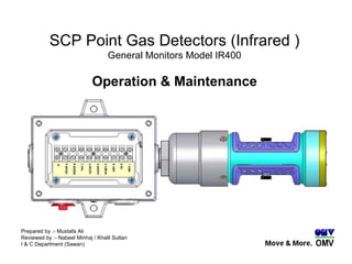
SCP Point Gas Detectors (Infrared ) General Monitors Model IR400 Operation & Maintenance Prepared by :- Mustafa Ali Reviewed by :- Nabeel Minhaj / Khalil Sultan I & C Department (Sawan)
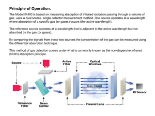
The Model IR400 is based on measuring absorption of infrared radiation passing through a volume of gas. uses a dual source, single detector measurement method. One source operates at a wavelength where absorption of a specific gas (or gases) occurs (the active wavelength). The reference source operates at a wavelength that is adjacent to the active wavelength but not absorbed by the gas (or gases).  By comparing the signals from these two sources the concentration of the gas can be measured using the differential absorption technique. This method of gas detection comes under what is commonly known as the non-dispersive infrared (NDIR) absorption principle.  Principle of Operation.
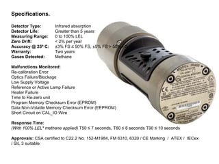
Specifications.  Detector Type:  Infrared absorption  Detector Life:  Greater than 5 years  Measuring Range:  0 to 100% LEL  Zero Drift: < 2% per year  Accuracy @ 25º C:  ±3% FS ≤ 50% FS, ±5% FS > 50% FS  Warranty:  Two years  Gases Detected:  Methane Malfunctions Monitored: Re-calibration Error  Optics Failure/Blockage  Low Supply Voltage  Reference or Active Lamp Failure  Heater Failure  Time to Re-zero unit  Program Memory Checksum Error (EPROM)  Data Non-Volatile Memory Checksum Error (EEPROM)  Short Circuit on CAL_IO Wire  Response Time: (With 100% LEL* methane applied)  T50 ≤ 7 seconds, T60 ≤ 8 seconds T90 ≤ 10 seconds  Approvals:  CSA certified to C22.2 No. 152-M1984, FM 6310, 6320 / CE Marking  /  ATEX /  IECex  / SIL 3 suitable
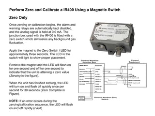
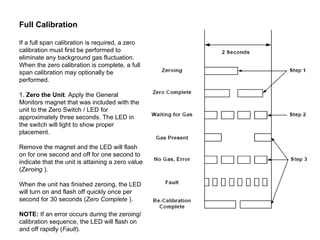
Once zeroing or calibration begins, the alarm and warning relays are automatically kept disabled, and the analog signal is held at 0.0 mA. The junction box used with the IR400 is fitted with a zero switch which eliminates any background gas fluctuation.  Zero Only Perform Zero and Calibrate a IR400 Using a Magnetic Switch Apply the magnet to the Zero Switch / LED for approximately three seconds. The LED in the switch will light to show proper placement.  Remove the magnet and the LED will flash on for one second and off for one second to indicate that the unit is attaining a zero value ( Zeroing  in the figure).  When the unit has finished zeroing, the LED will turn on and flash off quickly once per second for 30 seconds ( Zero Complete  in Figure). NOTE:  If an error occurs during the zeroing/calibration sequence, the LED will flash on and off rapidly ( Fault ).
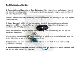
Full Calibration  If a full span calibration is required, a zero calibration must first be performed to eliminate any background gas fluctuation. When the zero calibration is complete, a full span calibration may optionally be performed.  1.  Zero the Unit . Apply the General Monitors magnet that was included with the unit to the Zero Switch / LED for approximately three seconds. The LED in the switch will light to show proper placement.  Remove the magnet and the LED will flash on for one second and off for one second to indicate that the unit is attaining a zero value ( Zeroing  ).  When the unit has finished zeroing, the LED will turn on and flash off quickly once per  second for 30 seconds ( Zero Complete  ).  NOTE:  If an error occurs during the zeroing/calibration sequence, the LED will flash on and off rapidly ( Fault ).
2.  Return to Normal Operation or Start Calibration.  If the magnet is not applied again, the unit will return to normal operation. To continue on and calibrate, apply the magnet again and the unit will enter the calibration mode. The LED will flash off quickly once every half-second while the unit is waiting for gas to be applied (Waiting for Gas).  3.  Apply Gas . Apply a 50% LEL gas using a Gas Check Kit with portable purge calibrator equipment (or 50% by volume of the gas being detected in nitrogen for units designed for monitoring 0 to 100% by volume).  When the unit detects the gas, the LED will flash on for a half second every one and one-half seconds ( Gas Present ).  If the unit does not detect the gas, the LED will flash off quickly once every half-second while the unit is still waiting for gas to be applied ( No Gas Error ).  Once calibration has been completed, the LED will turn on and flash off once every second ( Calibration Complete ). 4.  Return to Normal Operation . Remove the gas and the unit will return to normal operation once the gas has fallen below 5% of full scale.  Full Calibration Contd..
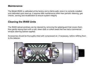
Maintenance   The Model IR400 is calibrated at the factory and is fail-to-safe; once it is correctly installed and calibrated upon start-up, it requires little maintenance other than periodic cleaning, gas checks, zeroing and recalibration to ensure system integrity  Cleaning the IR400 Units  The IR400 optical windows can be cleaned by removing the splashguard that covers them, then gently wiping them with a soft, clean cloth or cotton swab that has had a commercial window cleaning solution applied. Accessories should be thoroughly dried with compressed air, if necessary, before refitting them to the detector.
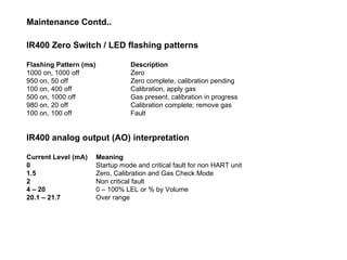
IR400 Zero Switch / LED flashing patterns  Flashing Pattern (ms)  Description  1000 on, 1000 off  Zero  950 on, 50 off  Zero complete, calibration pending  100 on, 400 off  Calibration, apply gas  500 on, 1000 off  Gas present, calibration in progress  980 on, 20 off  Calibration complete; remove gas  100 on, 100 off  Fault  IR400 analog output (AO) interpretation  Current Level (mA)  Meaning  0   Startup mode and critical fault for non HART unit  1.5   Zero, Calibration and Gas Check Mode  2  Non critical fault  4 – 20   0 – 100% LEL or % by Volume  20.1 – 21.7   Over range  Maintenance Contd..
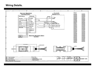
Wiring Details.

More Related Content

General Monitors Gdi Presentation

  • 1. SCP Point Gas Detectors (Infrared ) General Monitors Model IR400 Operation & Maintenance Prepared by :- Mustafa Ali Reviewed by :- Nabeel Minhaj / Khalil Sultan I & C Department (Sawan)
  • 2. The Model IR400 is based on measuring absorption of infrared radiation passing through a volume of gas. uses a dual source, single detector measurement method. One source operates at a wavelength where absorption of a specific gas (or gases) occurs (the active wavelength). The reference source operates at a wavelength that is adjacent to the active wavelength but not absorbed by the gas (or gases). By comparing the signals from these two sources the concentration of the gas can be measured using the differential absorption technique. This method of gas detection comes under what is commonly known as the non-dispersive infrared (NDIR) absorption principle. Principle of Operation.
  • 3. Specifications. Detector Type: Infrared absorption Detector Life: Greater than 5 years Measuring Range: 0 to 100% LEL Zero Drift: < 2% per year Accuracy @ 25º C: ±3% FS ≤ 50% FS, ±5% FS > 50% FS Warranty: Two years Gases Detected: Methane Malfunctions Monitored: Re-calibration Error Optics Failure/Blockage Low Supply Voltage Reference or Active Lamp Failure Heater Failure Time to Re-zero unit Program Memory Checksum Error (EPROM) Data Non-Volatile Memory Checksum Error (EEPROM) Short Circuit on CAL_IO Wire Response Time: (With 100% LEL* methane applied) T50 ≤ 7 seconds, T60 ≤ 8 seconds T90 ≤ 10 seconds Approvals: CSA certified to C22.2 No. 152-M1984, FM 6310, 6320 / CE Marking / ATEX / IECex / SIL 3 suitable
  • 4. Once zeroing or calibration begins, the alarm and warning relays are automatically kept disabled, and the analog signal is held at 0.0 mA. The junction box used with the IR400 is fitted with a zero switch which eliminates any background gas fluctuation. Zero Only Perform Zero and Calibrate a IR400 Using a Magnetic Switch Apply the magnet to the Zero Switch / LED for approximately three seconds. The LED in the switch will light to show proper placement. Remove the magnet and the LED will flash on for one second and off for one second to indicate that the unit is attaining a zero value ( Zeroing in the figure). When the unit has finished zeroing, the LED will turn on and flash off quickly once per second for 30 seconds ( Zero Complete in Figure). NOTE: If an error occurs during the zeroing/calibration sequence, the LED will flash on and off rapidly ( Fault ).
  • 5. Full Calibration If a full span calibration is required, a zero calibration must first be performed to eliminate any background gas fluctuation. When the zero calibration is complete, a full span calibration may optionally be performed. 1. Zero the Unit . Apply the General Monitors magnet that was included with the unit to the Zero Switch / LED for approximately three seconds. The LED in the switch will light to show proper placement. Remove the magnet and the LED will flash on for one second and off for one second to indicate that the unit is attaining a zero value ( Zeroing ). When the unit has finished zeroing, the LED will turn on and flash off quickly once per second for 30 seconds ( Zero Complete ). NOTE: If an error occurs during the zeroing/calibration sequence, the LED will flash on and off rapidly ( Fault ).
  • 6. 2. Return to Normal Operation or Start Calibration. If the magnet is not applied again, the unit will return to normal operation. To continue on and calibrate, apply the magnet again and the unit will enter the calibration mode. The LED will flash off quickly once every half-second while the unit is waiting for gas to be applied (Waiting for Gas). 3. Apply Gas . Apply a 50% LEL gas using a Gas Check Kit with portable purge calibrator equipment (or 50% by volume of the gas being detected in nitrogen for units designed for monitoring 0 to 100% by volume). When the unit detects the gas, the LED will flash on for a half second every one and one-half seconds ( Gas Present ). If the unit does not detect the gas, the LED will flash off quickly once every half-second while the unit is still waiting for gas to be applied ( No Gas Error ). Once calibration has been completed, the LED will turn on and flash off once every second ( Calibration Complete ). 4. Return to Normal Operation . Remove the gas and the unit will return to normal operation once the gas has fallen below 5% of full scale. Full Calibration Contd..
  • 7. Maintenance The Model IR400 is calibrated at the factory and is fail-to-safe; once it is correctly installed and calibrated upon start-up, it requires little maintenance other than periodic cleaning, gas checks, zeroing and recalibration to ensure system integrity Cleaning the IR400 Units The IR400 optical windows can be cleaned by removing the splashguard that covers them, then gently wiping them with a soft, clean cloth or cotton swab that has had a commercial window cleaning solution applied. Accessories should be thoroughly dried with compressed air, if necessary, before refitting them to the detector.
  • 8. IR400 Zero Switch / LED flashing patterns Flashing Pattern (ms) Description 1000 on, 1000 off Zero 950 on, 50 off Zero complete, calibration pending 100 on, 400 off Calibration, apply gas 500 on, 1000 off Gas present, calibration in progress 980 on, 20 off Calibration complete; remove gas 100 on, 100 off Fault IR400 analog output (AO) interpretation Current Level (mA) Meaning 0 Startup mode and critical fault for non HART unit 1.5 Zero, Calibration and Gas Check Mode 2 Non critical fault 4 – 20 0 – 100% LEL or % by Volume 20.1 – 21.7 Over range Maintenance Contd..