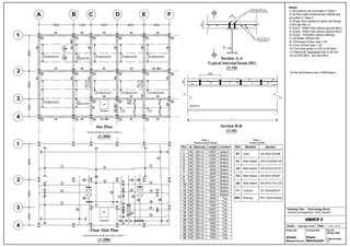
Genral arrangement of 2 floor building + RC floor system
- 1. Notes: 2 ├ś16 @ 250 c/c Stud welded to top flange 1) All sections are provided in Table 1 A B C D E F 30 2) All floor slab reinforcement details are provided in Table 2 3) Shear Stud welded to beam top flange: 80 8500 4300 6400 6600 6200 2 ├ś16 @ 250 c/c 4) Duct1: 1600x1200 (above ground floor) B1 B1 B1 B1 B1 5) Duct2: 1600x1200 (above ground floor) 1 C1 C1 C1 C1 C1 C1 H8 @ 350 c/c 6) Duct3: 1100x800 (whole building) 7) Lift Shaft: 2400x2100 G2, BR1 Reinforcement 8) Thickness of floor slab = 80 9) Cover of floor slab = 20 B1 G2 G2 G2 G2 G2 10) Concrete grade is C25 at 28 days 8800 11) Maximum Aggregate size is 20 mm B1 @spacing 2200 B1 B1 @spacing 2200 B1 @spacing 2200 B1 @spacing 2200 12) fy=275 MPa, fyk=300 MPa @spacing 2200 Section A-A Typical internal beam (B1) B1 B1 B1 B1 B1, BR1 (1:10) 2 C1 C1 C1 C1 C1 C1 250 All the dimensions are in Millimeters G1 G1 G3 G3 G3 80 6800 ct1 ct1 Du Du B1 @spacing 2267 B1 @spacing 2267 B1 @spacing 2267 G1 B1 B1 B1 3 ct B1 @spacing 2240 B1 C1 C1 C1 Du 2200 2200 3 G4 @spacing 2240 Lift G3, BR1 4400 BEAM B1 G3 B1 B1 2200 2200 Stairwell 4 C1 B1 C1 B1 C1 B1, BR1 C1 B1 C1 B1 L Site Plan Section B-B ( Section details provided in Table 1 ) (1:10) (1:200) Table 2 - Table 1 - 1 Reinforcement Details Ref. ├ś Spacing Length Location Ref. Member Section Details Section 1 H8 350 c/c 12000 Bottom B1 Joist UB 305x127x48 2 H8 350 c/c 12000 Bottom 14 350 c/c 3 H8 11000 Bottom 8800 350 c/c G1 Main Beam UB 610x305x149 4 H8 12000 Bottom 1 5 7 5 H8 350 c/c 12000 Bottom 6 H8 350 c/c 6500 Bottom G2 Main Beam UB 533x210x101 7 H8 350 c/c 9000 Bottom 8 H8 350 c/c 12000 Bottom G3 Main Beam UB 457x152x67 2 2 24 6 23 22 8 9 H8 350 c/c 6500 Bottom G4 Main Beam UB 457x191x133 10 H8 350 c/c 12000 Bottom 11 H8 350 c/c 9500 Bottom 3 13 9 12 H8 350 c/c 12000 Bottom C1 Column UC 254x254x73 6800 16 13 H8 350 c/c 4200 Bottom 17 18 25 14 H8 350 c/c 8500 Top BR1 Bracing PFC 300x100x54 19 20 4 10 15 H8 350 c/c 12000 Top 16 H8 350 c/c 7500 Top 3 15 11 17 H8 350 c/c 12000 Top Drawing Title: Technology Block Lift 21 18 H8 350 c/c 12000 Top General Arrangement / Floor System 4400 12 19 H8 350 c/c 7000 Top Stairwell 20 H8 350 c/c 12000 Top Group 5 21 H8 350 c/c 3000 Top 4 22 H8 350 c/c 3500 Top Scale : indicated under Date : 11 Dec. 2010 Floor Slab Plan 23 H8 350 c/c 7800 Top Drawn By: Checked By: Drg No. G5-GA-TB01 ( Reinforcement details provided in Table 2 ) 24 H8 350 c/c 3500 Top 25 H8 350 c/c 7000 Top Arash Ehsan Page Number: (1:200) Nassirpour Mehdizadeh 26

