


Gesture controlled vehicle part-1
- 1. GESTURE CONTROLLED VEHICLE PREPARED BY: VIMAL K VANKAR 1034 PRITESH B GOHIL 1005 GUIDED BY: NAZMA S NIZAMI
- 2. ’ü▒OBJECTIVE: ŌĆó To design model(vehicle) for the physically disabled person which is control by a movement of his hands.
- 3. ’ü▒INTRODUTION: ŌĆó Around 15% of the worlds population are disabled ŌĆó from last 10 year their have been revolutionary changes in technology. ŌĆó so with the advancements in technologies our aim is to make improvements in their personal mobility. ŌĆó we are using movements , directions of hand to control the vehicle.
- 6. ’ü▒COMPONENT LIST: ŌĆó Accelerometer Sensor ŌĆó Microcontroller ŌĆó Ultrasonic Sensor ŌĆó RF Transmitter and Receiver Module ŌĆó DC Motors ŌĆó Solar Plate ŌĆó Buzzer ŌĆó IRF510 MOSFET for Driver Circuit ŌĆó LED as an Indicator ŌĆó Power Supply
- 7. ’ü▒DETAILED DISCRIPTION 1. Accelerometer Sensor (ADXL345 Module) ’āśUltra Low Power ’āśUser-Selectable Resolution & Sensitivity ( Min 2g & Max 16g) ’āśData O/P of 3-Axis: X ,Y, Z. ’āśI2C Interface ’āśSmall and Thin: 3mm x 5mm x 1mm LGA package
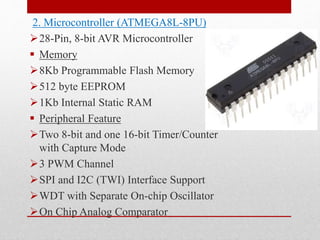
- 8. 2. Microcontroller (ATMEGA8L-8PU) ’āś28-Pin, 8-bit AVR Microcontroller ’é¦ Memory ’āś8Kb Programmable Flash Memory ’āś512 byte EEPROM ’āś1Kb Internal Static RAM ’é¦ Peripheral Feature ’āśTwo 8-bit and one 16-bit Timer/Counter with Capture Mode ’āś3 PWM Channel ’āśSPI and I2C (TWI) Interface Support ’āśWDT with Separate On-chip Oscillator ’āśOn Chip Analog Comparator
- 9. 3. Ultrasonic Sensor(HC-SR04) ’āśOffers Non-Contact Range Detection ’āśhigh accuracy and stable readings ’āśRange: 1ŌĆØ to 13 feet ’āśWith Ultrasonic Transmitter and Receiver Module ’āśEffectual Angle: <15┬░
- 10. 4. RF Transmitter and Receiver Module ’āśFor the transmission of accelerometer Data ’āśModulation Technique: ASK (On-Off Keyed) ’āśFrequency Range:315 / 433.92 MHZ. ’āślow cost, small size, and simple-to-use for designing
- 11. 5. DC Motors ’āśmotor is a CONVERETER ’āśGeared DC motor is required ’āś4 DC motor of same rating ’āśControlled by controller using PWM
- 12. 6. Solar Plate ’āśKind of PV cell ’āśUse for charging of battery ’āśRating: 12V 7. Buzzer ’āśIndicator ’āśUsed for the obstacle indication
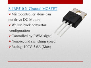
- 13. 8. IRF510 N-Channel MOSFET ’āśMicrocontroller alone can not drive DC Motors ’āśWe use buck convertor configuration ’āśControlled by PWM signal ’āśNenosecond switching speed ’āśRating: 100V, 5.6A (Max)
- 14. 9. LED ’āśFor the different indication purpose ’āśRating: 3V 10. Power Supply ’āśGives electrical power to all the components
- 15. ’ü▒TIMELINE ŌĆó At the end of this semester we mostly complete the hardware section. ŌĆó Rest programming and implementation on model will be done in next semester.
- 17. THANK YOU