Gyroscope, Gyroscopic Effect, Bike, ship, Planes
ŌĆó
0 likesŌĆó18 views

Gyroscope, Gyroscopic Effect, Bike, ship, Planes


Gyroscope, Gyroscopic Effect, Bike, ship, Planes
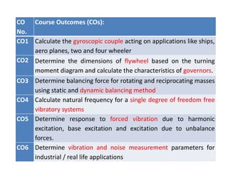
- 1. CO No. Course Outcomes (COs): CO1 Calculate the gyroscopic couple acting on applications like ships, aero planes, two and four wheeler CO2 Determine the dimensions of flywheel based on the turning moment diagram and calculate the characteristics of governors. CO3 Determine balancing force for rotating and reciprocating masses using static and dynamic balancing method CO4 Calculate natural frequency for a single degree of freedom free vibratory systems CO5 Determine response to forced vibration due to harmonic excitation, base excitation and excitation due to unbalance forces. CO6 Determine vibration and noise measurement parameters for industrial / real life applications
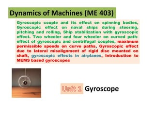
- 2. Gyroscopic couple and its effect on spinning bodies, Gyroscopic effect on naval ships during steering, pitching and rolling, Ship stabilization with gyroscopic effect. Two wheeler and four wheeler on curved path- effect of gyroscopic and centrifugal couples, maximum permissible speeds on curve paths, Gyroscopic effect due to lateral misalignment of rigid disc mounted on shaft, gyroscopic effects in airplanes, Introduction to MEMS based gyroscopes Dynamics of Machines (ME 403) Gyroscope
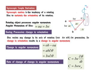
- 4. Gyroscopic motion is the tendency of a rotating Disc to maintain the orientation of its rotation. Rotating object possesses angular momentum Angular Momentum of Disc: Disc resists any change in its axis of rotation ( precession. So change in orientation results in a change in angular momentum ob oa ab Iw ’ü▒ ’ü▒ ’ĆĮ ’ĆŁ ’ĆĮ ’éČ ’ĆĮ ’éČ Rate of change of change in angular momentum Gyroscopic Couple Derivation During Precession change in orientation oa Iw ’ĆĮ ’ĆĮ Change in angular momentum p C Iw dt C Iww ’ü▒ ’éČ ’ĆĮ ’ĆĮ
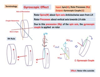
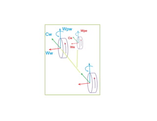
- 5. Terminology Gyroscopic Effect Rotor Spins(W) about Spin axis Anticlockwise seen from LH Rotor Precesses about vertical axis towards LH side Due to this precession (Wp) of the spin axis, the gyroscopic couple is applied on rotor RH Rule Effect: Rotor tilts outside Input: Spin(W), Rotor Precesses (Wp) Output: Gyroscopic Couple (C) C: Gyroscopic Couple
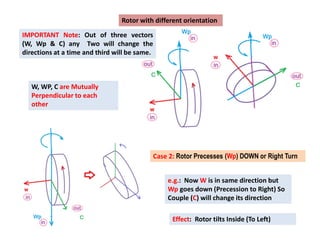
- 6. Rotor with different orientation e.g.: Now W is in same direction but Wp goes down (Precession to Right) So Couple (C) will change its direction IMPORTANT Note: Out of three vectors (W, Wp & C) any Two will change the directions at a time and third will be same. Effect: Rotor tilts Inside (To Left) W, WP, C are Mutually Perpendicular to each other Case 2: Rotor Precesses (Wp) DOWN or Right Turn
- 7. Gyroscopic Effect when Couple Input Output: Rotor Precesses (Wp) Perecesses to Left Side Input: Spin(W) Gyroscopic Couple (C) Application/Example: 1) Pitching movement in Ship/ Aero plane (Couple input) 2) Gyroscopic motion can cause catastrophic failure in wind turbines due to Couple input (Wind Air direction change) For Couple input Standard Diagram Direction of C is opposite
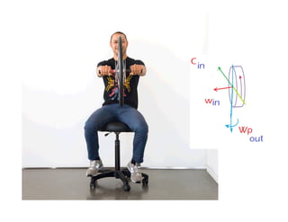
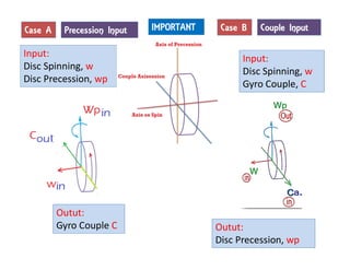
- 9. Case A Input: Disc Spinning, w Disc Precession, wp Outut: Gyro Couple C Case B Input: Disc Spinning, w Gyro Couple, C Outut: Disc Precession, wp IMPORTANT Precession Input Couple Input
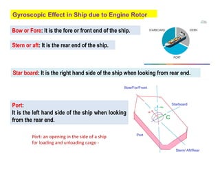
- 10. Gyroscopic Effect in Ship due to Engine Rotor Bow or Fore: It is the fore or front end of the ship. Stern or aft: It is the rear end of the ship. Port: It is the left hand side of the ship when looking from the rear end. Star board: It is the right hand side of the ship when looking from rear end. Port: an opening in the side of a ship for loading and unloading cargo -
- 11. Ship Terminology Rolling is a rotation of ship around a longitudinal axis, Tilting motion of the ship from Starboard to port Types of Movements Gyroscopic Effect on Naval Ship Pitching is a rotation of ship around the transverse axis Pitch describes the up and down motion of a vessel. This is characterized by the rising and falling of bow and stern. Steering(yawing) is a rotation of ship around the vertical axis.
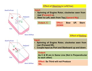
- 12. Effect of Steering to Left(Yaw) Input: ŌĆó Spinning of Engine Rotor, clockwise seen from rear (Forward w), ŌĆó Steer to Left, seen from Top,(Upward Wp) Output, C: Effect: Bow UP, Stern DOWN Input: ŌĆó Spinning of Engine Rotor, clockwise seen from rear (Forward W), ŌĆó Couple Input as Port and Starboard up and down Output: As C & W are in Same Line (Not in Perpendicular to each other) Effect: So Third will not Produce NIL Effect of Rolling
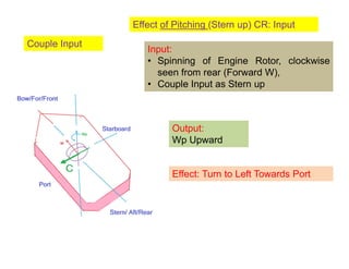
- 13. Effect of Pitching (Stern up) CR: Input Input: ŌĆó Spinning of Engine Rotor, clockwise seen from rear (Forward W), ŌĆó Couple Input as Stern up Output: Wp Upward Effect: Turn to Left Towards Port Couple Input
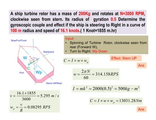
- 14. A ship turbine rotor has a mass of 200Kg and rotates at N=3000 RPM, clockwise seen from stern. Its radius of gyration 0.5 Determine the gyroscopic couple and effect if the ship is steering to Right in a curve of 100 m radius and speed of 16.1 knots.( 1 Knot=1855 m.hr) Input: ŌĆó Spinning of Turbine Rotor, clockwise seen from rear (Forward W), ŌĆó Turn to Right: Wp Down Effect: Stern UP p C I w w ’ĆĮ ’é┤ ’é┤ 2 314.158 60 N w RPS ’ü░ ’ĆĮ ’ĆĮ 2 2 2 2000(0.5) 500 I mk kg m ’ĆĮ ’ĆĮ ’ĆĮ ’ĆŁ 16.1 1855 5.295 / 3600 0.08295 p v m s v w RPS R ’é┤ ’ĆĮ ’ĆĮ ’ĆĮ ’ĆĮ 13031.28 p C I w w Nm ’ĆĮ ’é┤ ’é┤ ’ĆĮ Ans Ans
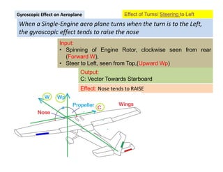
- 15. When a Single-Engine aero plane turns when the turn is to the Left, the gyroscopic effect tends to raise the nose Gyroscopic Effect on Aeroplane Effect of Turns/ Steering to Left Input: ŌĆó Spinning of Engine Rotor, clockwise seen from rear (Forward W), ŌĆó Steer to Left, seen from Top,(Upward Wp) Output: C: Vector Towards Starboard Effect: Nose tends to RAISE
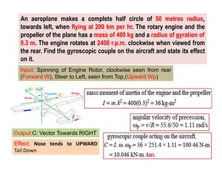
- 16. An aeroplane makes a complete half circle of 50 metres radius, towards left, when flying at 200 km per hr. The rotary engine and the propeller of the plane has a mass of 400 kg and a radius of gyration of 0.3 m. The engine rotates at 2400 r.p.m. clockwise when viewed from the rear. Find the gyroscopic couple on the aircraft and state its effect on it. Input: Spinning of Engine Rotor, clockwise seen from rear (Forward W), Steer to Left, seen from Top,(Upward Wp) Output:C: Vector Towards RIGHT Effect: Nose tends to UPWARD Tail:Down
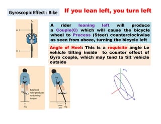
- 17. If you lean left, you turn left A rider leaning left will produce a Couple(C) which will cause the bicycle wheel to Precess (Steer) counterclockwise as seen from above, turning the bicycle left Gyroscopic Effect : Bike Angle of Heel: This is a requisite angle i.e vehicle tilting inside to counter effect of Gyro couple, which may tend to tilt vehicle outside
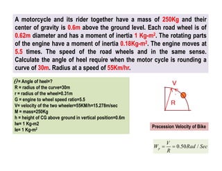
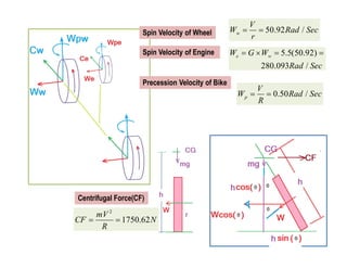
- 18. = Angle of heel=? R = radius of the curve=30m r = radius of the wheel=0.31m G = engine to wheel speed ratio=5.5 V= velocity of the two wheeler=55KM/h=15.278m/sec M = mass=250Kg h = height of CG above ground in vertical position=0.6m Iw= 1 Kg-m2 Ie= 1 Kg-m2 A motorcycle and its rider together have a mass of 250Kg and their center of gravity is 0.6m above the ground level. Each road wheel is of 0.62m diameter and has a moment of inertia 1 Kg-m2. The rotating parts of the engine have a moment of inertia 0.18Kg-m2. The engine moves at 5.5 times. The speed of the road wheels and in the same sense. Calculate the angle of heel require when the motor cycle is rounding a curve of 30m. Radius at a speed of 55Km/hr. ’ü▒ 0.50 / p V W Rad Sec R ’ĆĮ ’ĆĮ Precession Velocity of Bike
- 19. 2 1750.62 mV CF N R ’ĆĮ ’ĆĮ Centrifugal Force(CF) 50.92 / w V W Rad Sec r ’ĆĮ ’ĆĮ 0.50 / p V W Rad Sec R ’ĆĮ ’ĆĮ 5.5(50.92) 280.093 / e w W G W Rad Sec ’ĆĮ ’é┤ ’ĆĮ ’ĆĮ Spin Velocity of Wheel Spin Velocity of Engine Precession Velocity of Bike
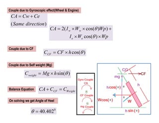
- 20. ( ) CA Cw Ce Same direction ’ĆĮ ’Ć½ cos( ) CF C CF h ’ü▒ ’ĆĮ ’é┤ sin( ) weight C Mg h ’ü▒ ’ĆĮ ’é┤ 2( cos( ) ) cos( ) w w e e CA I W Wp I W Wp ’ü▒ ’ü▒ ’ĆĮ ’é┤ ’é┤ ’Ć½ ’é┤ ’é┤ Couple due to Self weight (Mg) Couple due to CF Couple due to Gyroscopic effect(Wheel & Engine) Balance Equation CF Weight CA C C ’Ć½ ’ĆĮ 0 40.402 ’ü▒ ’ĆĮ On solving we get Angle of Heel
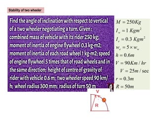
- 21. 2 2 250 1 0.3 5 0.6 90 / 25 / sec 0.3 50 w e e w M Kg I Kgm I Kgm w w h m V Km hr V m r m R m ’ĆĮ ’ĆĮ ’ĆĮ ’ĆĮ ’é┤ ’ĆĮ ’ĆĮ ’ĆĮ ’ĆĮ ’ĆĮ Stability of two wheeler
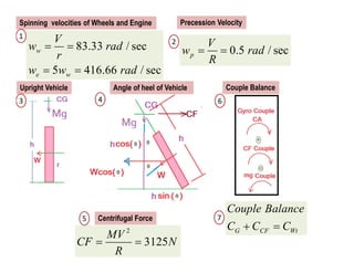
- 23. 83.33 / sec 5 416.66 / sec w e w V w rad r w w rad ’ĆĮ ’ĆĮ ’ĆĮ ’ĆĮ 0.5 / sec p V w rad R ’ĆĮ ’ĆĮ 2 3125 MV CF N R ’ĆĮ ’ĆĮ Spinning velocities of Wheels and Engine Precession Velocity G CF Wt Couple Balance C C C ’Ć½ ’ĆĮ Centrifugal Force Upright Vehicle Angle of heel of Vehicle Couple Balance 1 2 3 4 5 6 7
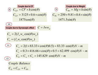
- 24. 2( cos( ) ) ( cos( ) ) w w w p e e e p C I w w C I w w ’ü▒ ’ü▒ ’ĆĮ ’ĆĮ 2(1 83.33 cos( )0.5) 83.33 cos( ) 0.3 416.66 cos( ) 0.5 62.499 cos( ) 145.829 cos( ) w e G w e C N m C N m C C C N m ’ü▒ ’ü▒ ’ü▒ ’ü▒ ’ü▒ ’ĆĮ ’é┤ ’é┤ ’ĆĮ ’ĆŁ ’ĆĮ ’é┤ ’é┤ ’é┤ ’ĆĮ ’ĆŁ ’ĆĮ ’Ć½ ’ĆĮ ’ĆŁ p C Iww ’ĆĮ G CF Wt Couple Balance C C C ’Ć½ ’ĆĮ cos( ) CF C CF h ’ü▒ ’ĆĮ ’é┤ 3125 0.6 cos( ) 1875cos( ) CF C ’ü▒ ’ü▒ ’ĆĮ ’é┤ ’é┤ sin( ) Wt C Mg h ’ü▒ ’ĆĮ ’é┤ 250 9.81 0.6 sin( ) 1471.5sin( ) Wt C ’ü▒ ’ü▒ ’ĆĮ ’é┤ ’é┤ ’é┤ Couple due to CF Couple due to Weight Couple due to Gyroscopic effect 8 9 10 11 12
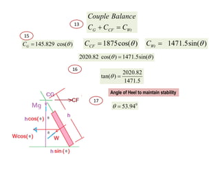
- 25. G CF Wt Couple Balance C C C ’Ć½ ’ĆĮ 145.829 cos( ) G C ’ü▒ ’ĆĮ 1875cos( ) CF C ’ü▒ ’ĆĮ 1471.5sin( ) Wt C ’ü▒ ’ĆĮ 2020.82 cos( ) 1471.5sin( ) ’ü▒ ’ü▒ ’ĆĮ 2020.82 tan( ) 1471.5 ’ü▒ ’ĆĮ 0 53.94 ’ü▒ ’ĆĮ Angle of Heel to maintain stability 13 15 16 17