ݺߣ

ݺߣShare a Scribd company logo
1/14/08 3:23 PMHD44780 24x2 Display Information
Page 1 of 6http://www.serialwombat.com/parts/lcd107.htm
Serial Wombat
a general-purpose digital interface device for hobbyists, engineers and students
Serial Wombat Home
WD-C2401P LCD
HD44780 24x2 LCD
Purchase A Wombat
HD44780 24x2 LCD panel With EL backlight
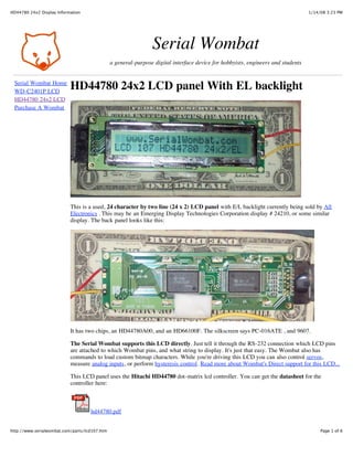
This is a used, 24 character by two line (24 x 2) LCD panel with E/L backlight currently being sold by All
Electronics . This may be an Emerging Display Technologies Corporation display # 24210, or some similar
display. The back panel looks like this:
It has two chips, an HD44780A00, and an HD66100F. The silkscreen says PC-016ATE , and 9607.
The Serial Wombat supports this LCD directly. Just tell it through the RS-232 connection which LCD pins
are attached to which Wombat pins, and what string to display. It's just that easy. The Wombat also has
commands to load custom bitmap characters. While you're driving this LCD you can also control servos,
measure analog inputs, or perform hysteresis control. Read more about Wombat's Direct support for this LCD...
This LCD panel uses the Hitachi HD44780 dot-matrix lcd controller. You can get the datasheet for the
controller here:
hd44780.pdf
1/14/08 3:23 PMHD44780 24x2 Display Information
Page 2 of 6http://www.serialwombat.com/parts/lcd107.htm
And the datasheet for this particular LCD (or compatible) display here:
LCD-107.pdf
Pros and Cons for this HD44780 based 2x24 LCD
Panel:
Pro: HD44780 controller is the most common on the planet.
Pro: Single +5 volt supply (contrast is voltage divider between +5 and ground)
Pro: Only requires 6 I/O pins to operate
Pro: Good documentation. Both the Pinout and the HD44780 controller documentation are readily
available.
Pro: This LCD doesn't appear to flicker when you update it rapidly.
Pro: Up to 8 user programmable characters are available.
Pro: The E/L Backlight looks groovy.
Pro: Uses a standard 14 pin (7x2) connector, on standard .1 spacing.
Con: E/L backlights require more external circuitry than LEDs if you only have DC current
Con: The Contrast on this LCD doesn't seem as good as some others (like the WD-C2401P). I got
the best contrast simply by attaching Vo to ground. Even then, you have to be about 30
degrees "below" the display to get a good contrast. This LCD is highly sensitive to the
viewer's position.
Con: The connector is wired backwards of the actual pinout. The red marked wire is 14, not 1.
Con:
Character set A0 is included on this display. It has lots of what look like East-Asian
characters to me. I like set A02 better.
Wiring up your LCD Display
The standard connector makes this a piece of cake. I simply stuck jumper wires in the appropriate holes, and
then covered the thing over with electical tape. I put the jumpers in my solderless breadboard. I used a 4-bit
interface, so I didn't wire DB0 through DB3.
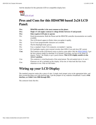
The connector looks like this:
1/14/08 3:23 PMHD44780 24x2 Display Information
Page 3 of 6http://www.serialwombat.com/parts/lcd107.htm
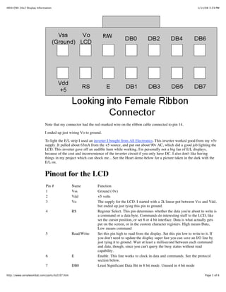
Note that my connector had the red-marked wire on the ribbon cable connected to pin 14.
I ended up just wiring Vo to ground.
To light the E/L strip I used an inverter I bought from All Electronics. This inverter worked good from my +5v
supply. It pulled about 63mA from the +5 source, and put out about 90v AC, which did a good job lighting the
LCD. This inverter gave off an audible hum while working. I'm personally not a big fan of E/L displays,
because of the cost and inconvenience of the inverter circuit if you only have DC. I also don't like having
things in my project which can shock me... See the Heart demo below for a picture taken in the dark with the
E/L on.
Pinout for the LCD
Pin # Name Function
1 Vss Ground ( 0v)
2 Vdd +5 volts
3 Vo The supply for the LCD. I started with a 2k linear pot between Vss and Vdd,
but ended up just tying this pin to ground.
4 RS Register Select. This pin determines whether the data you're about to write is
a command or a data byte. Commands do interesting stuff to the LCD, like
set the cursor position, or set 8 or 4 bit interface. Data is what actually gets
put on the screen, or in the custom character registers. High means Data,
Low means command
5 Read/Write Set this pin high to read from the display. Set this pin low to write to it. If
you don't need to update the display super fast you can save an I/O line by
just tying it to ground. Wait at least a millisecond between each command
and data, though, since you can't query the busy status without read
capability.
6 E Enable. This line works to clock in data and commands. See the protocol
section below.
7 DB0 Least Significant Data Bit in 8 bit mode. Unused in 4 bit mode
1/14/08 3:23 PMHD44780 24x2 Display Information
Page 4 of 6http://www.serialwombat.com/parts/lcd107.htm
8 DB1
9 DB2
10 DB3
11 DB4 Least significant bit in 4 bit mode
12 DB5
13 DB6
14 DB7 Most Significant Data Bit
4 bit Protocol for this 24x2 Hitachi HD44780 display
The protocol for this LCD is pretty simple.
To clock in a byte:
1. Set the E line low.
2. Set the RS line high if you're sending data, or low if your sending a command.
3. Set the E line high
4. Put the four most significant bits on DB4 to DB7
5. Set the E line low.
6. Set the E line high
7. Put the four least significant bits on DB4 to DB7.
8 Set the E line low The E line should remain low until you're ready to clock in another byte.
If you're using a microcontroller to do this, I'd make sure there was at least a microsecond between all of the
above steps, and at least a millisecond between clocked in bytes. This is a long time to wait, but you want to
be careful if you're hardwiring the Read/Write line low and not reading the busy status of the LCD.
Setting up the LCD to display characters:
Clock in the following bytes (cycle the reset line first, if you like):
RS Pin Value Function
Low 0x20 4 bit interface
Low 0x28 4 bit interface, two lines (you must send the 0x20 before this line)
Low 0xC0 Display On
Low 0x06 Cursor increment, no shift
Low 0x80 Display Address 0
Low 0x02 Cursor Home
Putting characters on the screen:
Set the RS line high, and clock in a data character. The LCD controller will auto-increment its address. You
can then send another character which will be put in the next character location. To reset the address to the first
character set the RS line low, then clock in 0x80. The first line goes from display addresses 0 to 23. The second
line starts at address 0x40. Therefore, to display all 48 characters, clock in command 0x80, then 24 data
characters, then command 0xC0, then 24 more data characters.
1/14/08 3:23 PMHD44780 24x2 Display Information
Page 5 of 6http://www.serialwombat.com/parts/lcd107.htm
The Character Set:
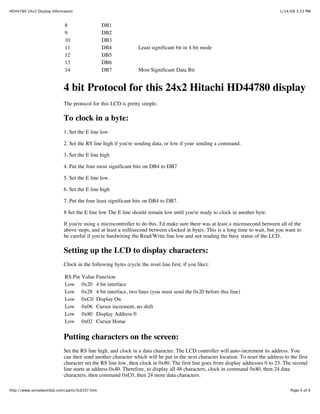
The characters from 0x20 (space) to 0x7F are standard ASCII. The other characters:
0x00 to 0x0F are reserved for user-definable bitmaps. Characters 0x10 to 0x1F are blank. This display supports
up to 8 user defined bitmaps.
0x80 to 0xAF:
0xB0 to 0xDF:
0xE0 to 0xFF:
Custom Characters:
The hd44780 allows the user to create up to 8 custom characters by sending bitmaps for the characters
appearance. The custom characters are available as 0x00, through 0x07 data. I used 6 custom characters to
make a big heart, and one to make a small heart:
This picture was taken in the dark with the E/L backlight active.
1/14/08 3:23 PMHD44780 24x2 Display Information
Page 6 of 6http://www.serialwombat.com/parts/lcd107.htm
Each character is 5 pixels wide, and 8 pixels tall. When sending bitmaps, send the top line first, followed by the
second line, and so on. The five least significant bits of each byte represent the five pixels, with the 2^4 bit
representing the leftmost pixel. The upper 3 bits of each byte are unused. A '1' bit represents a black pixel.
For example, the upper left segment of the heart would be made up of data 0x00, 0x03, 0x07, 0x0F,0x0F,
0x1F,0x1F,0x1F.
Pixel data is stored in the character RAM area. To set the pointer to the character RAM area, set the RS pin
low, and clock in the byte 0x40. Then set the RS pin high and clock in between 8 and 64 bytes of data,
depending on how many custom characters you want to use (8 bytes for each character). Issue the 0x80
command above to return to sending data into the standard string buffer.
Copyright Wombat Interface Products, 2006. All Rights Reserved.
Other Parts Directly Supported by the Serial Wombat:
WD-C2401P 24 x 1 LCD Panel
2x24 HD44780 Based Display w/
EL Backlight

More Related Content

Hd44780a00 dtasheet

  • 1. 1/14/08 3:23 PMHD44780 24x2 Display Information Page 1 of 6http://www.serialwombat.com/parts/lcd107.htm Serial Wombat a general-purpose digital interface device for hobbyists, engineers and students Serial Wombat Home WD-C2401P LCD HD44780 24x2 LCD Purchase A Wombat HD44780 24x2 LCD panel With EL backlight This is a used, 24 character by two line (24 x 2) LCD panel with E/L backlight currently being sold by All Electronics . This may be an Emerging Display Technologies Corporation display # 24210, or some similar display. The back panel looks like this: It has two chips, an HD44780A00, and an HD66100F. The silkscreen says PC-016ATE , and 9607. The Serial Wombat supports this LCD directly. Just tell it through the RS-232 connection which LCD pins are attached to which Wombat pins, and what string to display. It's just that easy. The Wombat also has commands to load custom bitmap characters. While you're driving this LCD you can also control servos, measure analog inputs, or perform hysteresis control. Read more about Wombat's Direct support for this LCD... This LCD panel uses the Hitachi HD44780 dot-matrix lcd controller. You can get the datasheet for the controller here: hd44780.pdf
  • 2. 1/14/08 3:23 PMHD44780 24x2 Display Information Page 2 of 6http://www.serialwombat.com/parts/lcd107.htm And the datasheet for this particular LCD (or compatible) display here: LCD-107.pdf Pros and Cons for this HD44780 based 2x24 LCD Panel: Pro: HD44780 controller is the most common on the planet. Pro: Single +5 volt supply (contrast is voltage divider between +5 and ground) Pro: Only requires 6 I/O pins to operate Pro: Good documentation. Both the Pinout and the HD44780 controller documentation are readily available. Pro: This LCD doesn't appear to flicker when you update it rapidly. Pro: Up to 8 user programmable characters are available. Pro: The E/L Backlight looks groovy. Pro: Uses a standard 14 pin (7x2) connector, on standard .1 spacing. Con: E/L backlights require more external circuitry than LEDs if you only have DC current Con: The Contrast on this LCD doesn't seem as good as some others (like the WD-C2401P). I got the best contrast simply by attaching Vo to ground. Even then, you have to be about 30 degrees "below" the display to get a good contrast. This LCD is highly sensitive to the viewer's position. Con: The connector is wired backwards of the actual pinout. The red marked wire is 14, not 1. Con: Character set A0 is included on this display. It has lots of what look like East-Asian characters to me. I like set A02 better. Wiring up your LCD Display The standard connector makes this a piece of cake. I simply stuck jumper wires in the appropriate holes, and then covered the thing over with electical tape. I put the jumpers in my solderless breadboard. I used a 4-bit interface, so I didn't wire DB0 through DB3. The connector looks like this:
  • 3. 1/14/08 3:23 PMHD44780 24x2 Display Information Page 3 of 6http://www.serialwombat.com/parts/lcd107.htm Note that my connector had the red-marked wire on the ribbon cable connected to pin 14. I ended up just wiring Vo to ground. To light the E/L strip I used an inverter I bought from All Electronics. This inverter worked good from my +5v supply. It pulled about 63mA from the +5 source, and put out about 90v AC, which did a good job lighting the LCD. This inverter gave off an audible hum while working. I'm personally not a big fan of E/L displays, because of the cost and inconvenience of the inverter circuit if you only have DC. I also don't like having things in my project which can shock me... See the Heart demo below for a picture taken in the dark with the E/L on. Pinout for the LCD Pin # Name Function 1 Vss Ground ( 0v) 2 Vdd +5 volts 3 Vo The supply for the LCD. I started with a 2k linear pot between Vss and Vdd, but ended up just tying this pin to ground. 4 RS Register Select. This pin determines whether the data you're about to write is a command or a data byte. Commands do interesting stuff to the LCD, like set the cursor position, or set 8 or 4 bit interface. Data is what actually gets put on the screen, or in the custom character registers. High means Data, Low means command 5 Read/Write Set this pin high to read from the display. Set this pin low to write to it. If you don't need to update the display super fast you can save an I/O line by just tying it to ground. Wait at least a millisecond between each command and data, though, since you can't query the busy status without read capability. 6 E Enable. This line works to clock in data and commands. See the protocol section below. 7 DB0 Least Significant Data Bit in 8 bit mode. Unused in 4 bit mode
  • 4. 1/14/08 3:23 PMHD44780 24x2 Display Information Page 4 of 6http://www.serialwombat.com/parts/lcd107.htm 8 DB1 9 DB2 10 DB3 11 DB4 Least significant bit in 4 bit mode 12 DB5 13 DB6 14 DB7 Most Significant Data Bit 4 bit Protocol for this 24x2 Hitachi HD44780 display The protocol for this LCD is pretty simple. To clock in a byte: 1. Set the E line low. 2. Set the RS line high if you're sending data, or low if your sending a command. 3. Set the E line high 4. Put the four most significant bits on DB4 to DB7 5. Set the E line low. 6. Set the E line high 7. Put the four least significant bits on DB4 to DB7. 8 Set the E line low The E line should remain low until you're ready to clock in another byte. If you're using a microcontroller to do this, I'd make sure there was at least a microsecond between all of the above steps, and at least a millisecond between clocked in bytes. This is a long time to wait, but you want to be careful if you're hardwiring the Read/Write line low and not reading the busy status of the LCD. Setting up the LCD to display characters: Clock in the following bytes (cycle the reset line first, if you like): RS Pin Value Function Low 0x20 4 bit interface Low 0x28 4 bit interface, two lines (you must send the 0x20 before this line) Low 0xC0 Display On Low 0x06 Cursor increment, no shift Low 0x80 Display Address 0 Low 0x02 Cursor Home Putting characters on the screen: Set the RS line high, and clock in a data character. The LCD controller will auto-increment its address. You can then send another character which will be put in the next character location. To reset the address to the first character set the RS line low, then clock in 0x80. The first line goes from display addresses 0 to 23. The second line starts at address 0x40. Therefore, to display all 48 characters, clock in command 0x80, then 24 data characters, then command 0xC0, then 24 more data characters.
  • 5. 1/14/08 3:23 PMHD44780 24x2 Display Information Page 5 of 6http://www.serialwombat.com/parts/lcd107.htm The Character Set: The characters from 0x20 (space) to 0x7F are standard ASCII. The other characters: 0x00 to 0x0F are reserved for user-definable bitmaps. Characters 0x10 to 0x1F are blank. This display supports up to 8 user defined bitmaps. 0x80 to 0xAF: 0xB0 to 0xDF: 0xE0 to 0xFF: Custom Characters: The hd44780 allows the user to create up to 8 custom characters by sending bitmaps for the characters appearance. The custom characters are available as 0x00, through 0x07 data. I used 6 custom characters to make a big heart, and one to make a small heart: This picture was taken in the dark with the E/L backlight active.
  • 6. 1/14/08 3:23 PMHD44780 24x2 Display Information Page 6 of 6http://www.serialwombat.com/parts/lcd107.htm Each character is 5 pixels wide, and 8 pixels tall. When sending bitmaps, send the top line first, followed by the second line, and so on. The five least significant bits of each byte represent the five pixels, with the 2^4 bit representing the leftmost pixel. The upper 3 bits of each byte are unused. A '1' bit represents a black pixel. For example, the upper left segment of the heart would be made up of data 0x00, 0x03, 0x07, 0x0F,0x0F, 0x1F,0x1F,0x1F. Pixel data is stored in the character RAM area. To set the pointer to the character RAM area, set the RS pin low, and clock in the byte 0x40. Then set the RS pin high and clock in between 8 and 64 bytes of data, depending on how many custom characters you want to use (8 bytes for each character). Issue the 0x80 command above to return to sending data into the standard string buffer. Copyright Wombat Interface Products, 2006. All Rights Reserved. Other Parts Directly Supported by the Serial Wombat: WD-C2401P 24 x 1 LCD Panel 2x24 HD44780 Based Display w/ EL Backlight