How The Opal Ice Maker Was Built
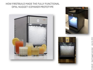
- 1. irstBuildOpalNuggetIcemakerJuly16,2015 HOW FIRSTBUILD MADE THE FULLY FUNCTIONAL OPAL NUGGET ICEMAKER PROTOTYPE
- 2. irstBuildOpalNuggetIcemakerJuly16,2015 MAJOR PIECES OF THE PROTOTYPE 3D printed and post- foamed assembly CNC machined and post painted modulan bottom and top Waterjet and CNC press brake brushed stainless steel outer skin Refrigerant system and icemaker structure
- 3. irstBuildOpalNuggetIcemakerJuly16,2015 Our refrigerant subsystem was created by hacking up an existing countertop icemaker. The refrigerant was removed, the system was reconfigured, and the new system was recharged with fresh R134a refrigerant. This section was removed This valve was removed The compressor was used The fan, condenser and dryer were used HOW WE MADE THE REFRIGERANT SUBSYSTEM
- 4. irstBuildOpalNuggetIcemakerJuly16,2015 First an internal frame was built to hold all the icemaker “guts”. HOW WE MADE THE REFRIGERANT SUBSYSTEM
- 5. irstBuildOpalNuggetIcemakerJuly16,2015 Next the condenser, fan and filter from the hacked system are mounted to the frame. Filter drawn to show where it is located Fan is between the condenser and the mounting frame HOW WE MADE THE REFRIGERANT SUBSYSTEM
- 6. irstBuildOpalNuggetIcemakerJuly16,2015 The evaporator section of the refrigerant system is tightly wrapped around the icemaker cylinder. HOW WE MADE THE REFRIGERANT SUBSYSTEM
- 7. irstBuildOpalNuggetIcemakerJuly16,2015 The icemaker cylinder is covered over with a piece of PVC pipe and insulated with “great stuff” expanding foam. Then it is reassembled and recharged. Here is the full refrigerant system assembled and cooling. You can see frost forming on some of the refrigerant lines. HOW WE MADE THE REFRIGERANT SUBSYSTEM
- 8. irstBuildOpalNuggetIcemakerJuly16,2015 HOW WE MADE THE REFRIGERANT SYSTEM Here is another view with the icemaking system fully put together. All the key components of the working system are now in place.
- 9. irstBuildOpalNuggetIcemakerJuly16,2015 Picture of the foamed assembly (before we added foam). It consists of two parts, the top and the body. Each was printed on a 3D printer. They are hollow and have holes to allow “great stuff” expanding foam to be squirted in. HOW WE MADE THE INSULATED SUBSYSTEM
- 10. irstBuildOpalNuggetIcemakerJuly16,2015 Here is a good view of all the pieces assembled into a functional structure. The refrigerant lines have been insulated as necessary. THE GUTS ALL PUT TOGETHER
- 11. irstBuildOpalNuggetIcemakerJuly16,2015 First step is to waterjet the blank out of stainless steel The stainless blank is then sanded with sanding pads to get the brushed appearance Next the blank is bent to shape using the CNC press brake Finally graphics are applied HOW WE MADE THE OUTER SKIN
- 12. irstBuildOpalNuggetIcemakerJuly16,2015 CONTROL SYSTEM The icemaker needs electronic controls for the user interface and overall operation of the system. The board was custom made on our board mill. An Arduino Micro is used. An electronics case was also 3D printed. Wire harnesses were made by hand and everything was hooked up. The light ring is 12 LEDs behind a while acrylic diffuser that was machined on our CNC mill.
- 13. irstBuildOpalNuggetIcemakerJuly16,2015 Now everything has to get put together. BRINGING IT ALL TOGETHER


