Hydrostatic transmissions
•Download as PPT, PDF•
5 likes•5,482 views

Hydrostatic transmissions use a pump and motor connected in a hydraulic circuit to transmit power. They have four basic configurations: in-line, U-shaped, S-shaped, and split. Hydrostatic transmissions offer advantages like operating over a wide speed range without changing the prime mover speed and providing dynamic braking. They use either an open or closed hydraulic circuit and precisely control fluid flow and motor speed through variable displacement pumps and swash plates.


Hydrostatic transmissions
- 2. Hydrostatic Operation ÔÅÆ Hydrostatic transmissions are a pump and motor connected in a circuit together ÔÅÆ Most are constructed using piston pumps and piston motors ÔÅÆ Four basic configurations: ÔÅÆ In-line ÔÅÆ U-shaped ÔÅÆ S-shaped ÔÅÆ Split
- 3. In-Line Configuration ÔÅÆ The pump is directly connected to the motor ÔÅÆ All fluid is contained within the pump/motor combination ÔÅÆ Usually uses a variable pump and a constant displacement motor
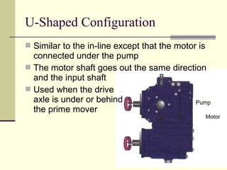
- 4. U-Shaped Configuration ÔÅÆ Similar to the in-line except that the motor is connected under the pump ÔÅÆ The motor shaft goes out the same direction and the input shaft ÔÅÆ Used when the drive axle is under or behind the prime mover
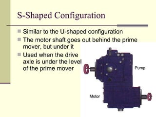
- 5. S-Shaped Configuration ÔÅÆ Similar to the U-shaped configuration ÔÅÆ The motor shaft goes out behind the prime mover, but under it ÔÅÆ Used when the drive axle is under the level of the prime mover
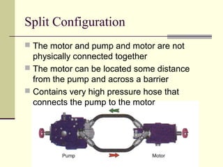
- 6. Split Configuration ÔÅÆ The motor and pump and motor are not physically connected together ÔÅÆ The motor can be located some distance from the pump and across a barrier ÔÅÆ Contains very high pressure hose that connects the pump to the motor
- 7. Advantages of Hydrostatic Transmissions ÔÅÆ It offers the ability to operate over a wide range of speeds without changing the prime mover speed ÔÅÆ It can change speeds rapidly because there are no large parts which add inertia ÔÅÆ It provide dynamic braking ÔÅÆ There is no interruption of power to the wheels when shifting
- 8. Hydrostatic Circuits ÔÅÆ Open circuit ÔÅÆ All fluid comes from the tank and is pumped to the motor ÔÅÆ When the fluid leaves the motor, it goes back to the tank ÔÅÆ Does not require a charge pump
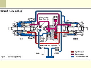
- 9. Hydrostatic Circuits ÔÅÆ Closed circuit ÔÅÆ The fluid is pumped to the motor ÔÅÆ As the fluid leaves the motor, it is returned to the pump inlet ÔÅÆ Requires a charge pump
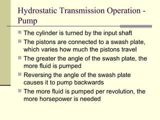
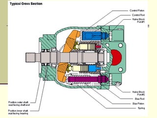
- 11. Hydrostatic Transmission Operation - Pump ÔÅÆ The cylinder is turned by the input shaft ÔÅÆ The pistons are connected to a swash plate, which varies how much the pistons travel ÔÅÆ The greater the angle of the swash plate, the more fluid is pumped ÔÅÆ Reversing the angle of the swash plate causes it to pump backwards ÔÅÆ The more fluid is pumped per revolution, the more horsepower is needed
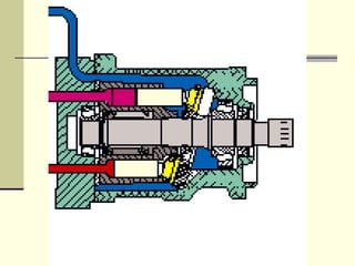
- 13. Hydrostatic Transmission Operation - Motor ÔÅÆ The motor accepts the fluid from the pump and turns a differential or wheel, depending on the configuration ÔÅÆ When the pump reverses direction, the motor turns backwards, giving you reverse ÔÅÆ Not all hydrostats are designed to pump backwards ÔÅÆ Many motors use a shuttle valve to reverse the flow of hydraulic fluid
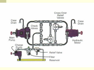
- 15. Hydrostatic Transmission Components ÔÅÆ All circuit types require a relief valve to prevent overpressurizing during dynamic braking ÔÅÆ The pump and motor have case drain lines to keep fluid that leaks internally from building pressure behind the piston ÔÅÆ Case drains are connected to the tank ÔÅÆ Charge pumps must provide enough fluid to replace leakage and cool the pump/motor assembly
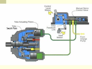
- 17. Servo Activated Hydrostatic Transmissions ÔÅÆ In larger hydrostats, the swash plate can be hard to move ÔÅÆ In these systems, a small piston assembly is attached to the swash plate and activated by low pressure (300 PSI) ÔÅÆ These servos are controlled by a small shuttle, making it easier to move the swash plate
- 19. Hydrostatic Transmission Testing ÔÅÆ Use a flow meter hooked to the case drain line to measure to output. It should be below the charge pump volume ÔÅÆ All hydrostatic transmissions have tight tolerances. The filters should be change at regular intervals ÔÅÆ Many systems have a pressure sensor that shuts down the prime mover if the charge pressure falls below a certain level
- 20. Hydrostatic Transmission Testing ÔÅÆ If the prime mover has a problem, it could fail to supply the needed power to the hydrostat ÔÅÆ Always rule out the prime mover first when checking for insufficient power problems ÔÅÆ Charge pressure varies, but should be between 160 to 300 PSI