Introduction of OpenSees
- 1. Welcome all for - One week Workshop on OpenSees at IIT Gandhinagar By Dhanaji S. Chavan, Assistant Professor, Department of Civil Engg., TKIET, Warananagar (Maharashtra) 1Dhanaji S. Chavan
- 2. OpenSees: Open System for Earthquake Engineering Simulation a software simulate the seismic response of structural and geotechnical system What is OpenSees ? 2Dhanaji S. Chavan
- 3. Developed as the computational platform for research in performance-based earthquake engineering at the “ Pacific Earthquake Engineering Resesrch Center” is also the simulation component for the NEESit since 2004 3Dhanaji S. Chavan
- 4. ÔÇó Advanced capabilities for modeling and analyzing the nonlinear response of systems using a wide range of : i. Material models ii. Elements iii. Solution algorithms ÔÇó Parallel computing to allow scalable simulations on high-end computers or for parameter studies 4Dhanaji S. Chavan
- 5. ÔÇó Modeling: ÔÉò Beam-column elements ÔÉò Continuum elements ÔÉò Wide range of uniaxial materials and section models for beam-columns. 5Dhanaji S. Chavan
- 6. ÔÇó Analysis: ÔÇß nonlinear analysis requires a wide range of algorithms and solution methods ÔÇó Provides ÔÇß nonlinear static and dynamic methods ÔÇß Equation solvers ÔÇß Methods for handling constraints 6Dhanaji S. Chavan
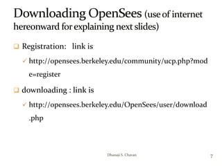
- 7.  Registration: link is  http://opensees.berkeley.edu/community/ucp.php?mod e=register  downloading : link is  http://opensees.berkeley.edu/OpenSees/user/download .php 7Dhanaji S. Chavan
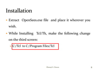
- 8. ÔÇó Extract OpenSees.exe file and place it wherever you wish. ÔÇó While Installing Tcl/Tk, make the following change on the third screen: ÔÉò C:/Tcl to C:/Program Files/Tcl 8Dhanaji S. Chavan
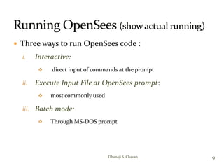
- 9.  Three ways to run OpenSees code : i. Interactive:  direct input of commands at the prompt ii. Execute Input File at OpenSees prompt:  most commonly used iii. Batch mode:  Through MS-DOS prompt 9Dhanaji S. Chavan
- 10. ÔÇó What is the deflection of the free end of a 3 m cantilever beam subjected to a point load of 100 kN? (The modulus of elasticity, E =2*1005 kN/m2) How to do coding for this problem in OpenSees????? 3m 100kN 10Dhanaji S. Chavan
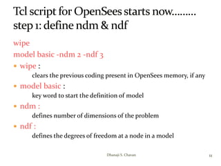
- 11. wipe model basic -ndm 2 -ndf 3 ÔÇó wipe : clears the previous coding present in OpenSees memory, if any ÔÇó model basic : key word to start the definition of model ÔÇó ndm : defines number of dimensions of the problem ÔÇó ndf : defines the degrees of freedom at a node in a model 11Dhanaji S. Chavan
- 12. ÔÇó ndm: number of dimensions we have to specify whether problem is 2-dimensional or 3- dimensional. How to determine whether problem is 2-D or 3-D: If to specify the geometry of the problem only two coordinates x and y are required , it is 2-D problem If to specify the geometry of the problem three coordinates x,y and z are required , it is 3-D problem In present case ndm is 2 12Dhanaji S. Chavan
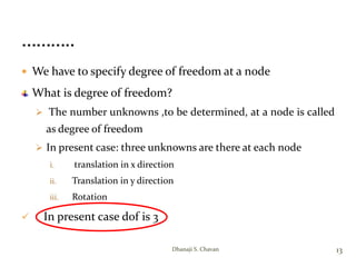
- 13.  We have to specify degree of freedom at a node What is degree of freedom?  The number unknowns ,to be determined, at a node is called as degree of freedom  In present case: three unknowns are there at each node i. translation in x direction ii. Translation in y direction iii. Rotation  In present case dof is 3 13Dhanaji S. Chavan
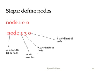
- 14. node 1 0 0 node 2 3 0 14Dhanaji S. Chavan Command to define node Node number X coordinate of node Y coordinate of node
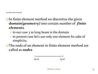
- 15. In finite element method we discretize the given domain(geometry) into certain number of finite elements.  in our case 3 m long beam is the domain  in present case let’s use only one element for sake of simplicity. The ends of an element in finite element method are called as nodes 15Dhanaji S. Chavan 1 2 (0,0) (3,0)
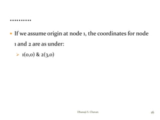
- 16. ÔÇó If we assume origin at node 1, the coordinates for node 1 and 2 are as under: ÔÉò 1(0,0) & 2(3,0) 16Dhanaji S. Chavan
- 17. fix 1 1 1 1 17Dhanaji S. Chavan Command to define fixity Node number Constrain x-translation Constrain y-translation Constrain rotation 
- 18. ÔÇó In our case boundary condition is : node 1 is fixed i.e. ÔÉò No translation in x direction ÔÉò No translation in y direction ÔÉò No rotation 18Dhanaji S. Chavan
- 19. element elasticBeamColumn 1 1 2 0.25 2.1e5 0.0052 1 19Dhanaji S. Chavan
- 20.  Which finite element to use to model the behavior of beam? Why?  OpenSees has wide range of elements in its library  Is it fine if we use any element from it?  Or we have to choose certain element only  How to decide which element to use ? …………..Needs some thinking…@ FEM…???????? 20Dhanaji S. Chavan
- 21. 1-d element : ÔÉò Used for geometries for which one of the dimensions is quite larger than rest two. ÔÉò E.g. beam : in case of beam its length is considerably larger than its breadth and depth. i.e. x >>> y, z ÔÉò In FEM such geometry is represented by just a line. When the element is created by connecting two nodes, software comes to know about only one out of 3 dimensions. Remaining two dimensions i.e. cross sectional area must be defined as additional input data & assigned to respective element. 21Dhanaji S. Chavan
- 22. 2-d element: ÔÉò Two dimensions are quite larger than third one ÔÉò E.g. metal plate: length & width are considerably larger than thickness. i.e. x, y >>> z ÔÉò The third dimension i.e. thickness has to be provided as additional input in coding by user & assigned to respective element. 22Dhanaji S. Chavan
- 23. 3-d element: ÔÉò All three dimensions are comparable ÔÉò E.g. brick: x~y~z ÔÉò No additional dimension to be defined. While meshing itself all three dimensions are included. 23Dhanaji S. Chavan
- 24.  In our case, we understood that we have to use 1-d element.  Which 1-d element should we use?  Should we use spring element?  Or bar/truss element?  Or beam element Think……………….????????????? 24Dhanaji S. Chavan
- 25. In present case,  Shear force &  Bending moment will be developed in the cantilever beam.  We have to choose 1-d finite element in such a way that it will take both shear force & bending moment 25Dhanaji S. Chavan
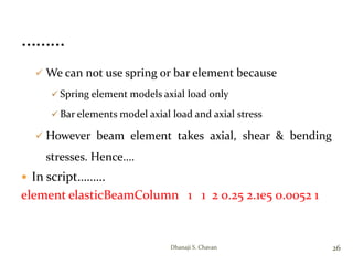
- 26.  We can not use spring or bar element because  Spring element models axial load only  Bar elements model axial load and axial stress  However beam element takes axial, shear & bending stresses. Hence….  In script……… element elasticBeamColumn 1 1 2 0.25 2.1e5 0.0052 1 26Dhanaji S. Chavan
- 27. Different materials behave differently when subjected to load.  This behavior is represented by stress-strain curves. e.g. 27Dhanaji S. Chavan   Elastic Spring   Mild Steel
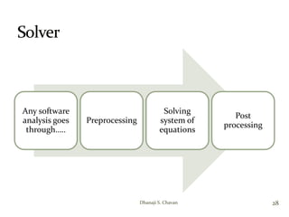
- 28. Any software analysis goes through….. Preprocessing Solving system of equations Post processing 28Dhanaji S. Chavan
- 29. ÔÇó Solver takes the data generated in preprocessing, process(solve) it using specific algorithms and give an output as a result of analysis. ÔÇó Solver is brain of any software 29Dhanaji S. Chavan
- 30. Types of solvers • Direct solvers:(based on Gauss elimination/ LU decomposition) • Iterative solvers: • error is minimized & solution is converged through iterative calculations • User has to set convergence tolerance • Three types of tolerances: displacement , load, work • Method used for convergence: Newton Raphson, modified Newton raphson etc. 30Dhanaji S. Chavan

