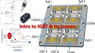
Introduction to IGBT & its losses with videos demonstration
- 1. Intro to IGBT & its Losses:
- 2. Presenters: Zeeshan Akhtar ID # 6118000011 Modern Electric Drive Automatic Control System : Sir: Chi Yan Bo /łµŃÓ˛© Tianjin University,China
- 3. Contents: ? General Introduction to IGBT ? IGBT Equivalent Circuit ? IGBT Output Characteristics ? IGBT usage as a Switch ? IGBT Datasheet ? IGBT Applications ? IGBT Power Losses ? Some FAQs about IGBTs ? References ? Q & A Session Note: Presentation include some videos for demonstration taken from different sources
- 4. IGBT: Insulated-Gate Bipolar Transistor ? Combination BJT and MOSFET ? High Input Impedance (MOSFET) ? Low On-state Conduction Losses (BJT) ? High Voltage and Current Ratings ? Symbol
- 5. Cross-Sectional View of an IGBT:
- 7. IGBT Equivalent Circuit for VGE<VT + VCCIEPNP ICPNP IBPNP ICNPN IENPN IBNPN Leakage Current IRBE Both transistors are OFF
- 8. IGBT Equivalent Circuit for VGE>VT : + VCC NPN Transistor becomes forward biased at the BE, drawing current from the Base of the PNP transistor. MOS transistor conducts, drawing current from the Base of the PNP transistor. PNP transistor turns ON, RMOD decreases due to carrier injection from the PNP Emitter.
- 9. Channel is Induced When VGE>VT : Induced Channel electrons RMOD PNP RBE NPN
- 12. IGBT Output Characteristics Follows an SCR characteristic
- 14. IGBT Used as a Switch:
- 15. Electro mechanical Relay Operating from IGBT:
- 38. Power Losses in an IGBT Module : Power loss in an IGBT mainly consists of steady ¨C state conduction loss and switching loss. The switching loss in the IGBT is given by Esw= Eon + Eoff whereas, in the Diode it is given by the reverse recovery loss. All these switching energies can be added together multiplied by the switching frequency to give the total module switching losses. The conduction losses for the IGBT and free- wheeling diode are the product of the current flowing through the collector or anode and saturation voltage (on state voltage) over the conducting period. In contrast, the switching losses happen as a result of energy loss during the transition and switching frequency.
- 39. Power Losses in an IGBT Module : ? IGBTs works in two states and produce losses in those states; conduction losses and switching losses. ? Conduction losses mainly depend on the duty cycle, load current and junction temperature, whereas, switching losses depends on the load current, dc link voltage, junction temperature and switching frequency. If the switching frequency is higher, then the losses will be higher. Power losses for different stages give significant amount of power loss in an IGBT module if driven carefully. ? The total average power of the IGBT is the sum of the conduction loss, turn on and turn off losses as shown in Eqn.1 Pavg.IGBT = Pcond + Pon + Poff + Pthermal
- 40. Power Losses in an IGBT Module :
- 62. Reverences: ? Google ? Wekipedia ? şÝşÝߣplayer ? Fujielectric ? Mitsubishi ? Semikron ? www3.ntu.edu.sg ? YouTube


