

Keypad based door lock system
- 1. ECWAY TECHNOLOGIES IEEE PROJECTS & SOFTWARE DEVELOPMENTS OUR OFFICES @ CHENNAI / TRICHY / KARUR / ERODE / MADURAI / SALEM / COIMBATORE BANGALORE / HYDRABAD CELL: 9894917187 | 875487 1111/2222/3333 | 8754872111 / 3111 / 4111 / 5111 / 6111 Visit: www.ecwayprojects.com Mail to: ecwaytechnologies@gmail.com KEYPAD BASED DOOR LOCK SYSTEM INTRODUCTION: The goal of this project was to design and develop an electronic door lock, which is controlled by a 4-digit password entered by the user. The password is entered using a standard 16-button keypad, which is mounted on the door. Basically, the functionality of this device can be seen once the correct password is entered. The user then has a choice between unlocking the door and changing the current password. By unlocking the door, the locking mechanism remains open for about 20 seconds. Once the 20-second time interval elapses, the door lock automatically returns to the locked position. Upon changing the current password, the new password is valid immediately. The main features of this electronic door lock are its high reliability, low operating power consumption, and ease of use. Thus, this electronic locking mechanism definitely possesses marketable potential.
- 2. OBJECTIVE: This electronic door lock design is intended to have low operating power consumption. With this in mind, we designed the door lock to retract or unlock only when 5 volts are applied to it. Thus, the door lock consumes power only when it is unlocked for those 20-second intervals. This design is also useful in the event of a power outage in that you can be assured that your door will remain locked, which is particularly comforting when you may be asleep or on a trip away from home. One design specification that was reformulated in our final design was the use of a solid state relay in place of the simple amplifier we had originally proposed.
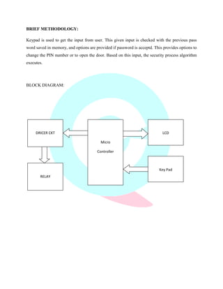
- 3. BRIEF METHODOLOGY: Keypad is used to get the input from user. This given input is checked with the previous pass word saved in memory, and options are provided if password is acceptd. This provides options to change the PIN number or to open the door. Based on this input, the security process algorithm executes. BLOCK DIAGRAM: DRICER CKT LCD Micro Controller RELAY Key Pad
- 4. HARDWARE REQUIREMENTS: - ’éĘ ATMega16. ’éĘ Step down transformer (230 V-12V). ’éĘ Relay. ’éĘ LCD display. ’éĘ Voltage regulator. ’éĘ Rectifier. SOFTWARE REQUIREMENTS: - ’éĘ Codevision AVR. ’éĘ Sinaprog