ݺߣ

ݺߣShare a Scribd company logo
01I551-GB
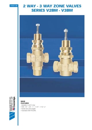
               2 WAY - 3 WAY ZONE VALVES
                  SERIES V2BM - V3BM


            MAIN
            FEATURES
            - Available 2 and 3 way:
            • DN: 1/2” - 3/4” - 1” - 1.1/4” - 1.1/2”- 2”
            • Small sizes and weigth
            • Standard UNI 9753/90
DESCRIPTION                                                                       V2BM                   Part No.          Dn           Weight
V2BM, V3BM are zone valves, 2 way and 3 way,                                      2 way globe valve,                                     (g)
manufactured in bronze with a globe plug. The valves are                          normally open          V2BM15         1/2"             1250
suitable for actuator series M400 or M800. The valves are                                                V2BM20         3/4"             1250
availables with female threated. V2BM is normally open.                                                  V2BM25          1"              1650
                                                                                                         V2BM32        1.1/4"            2050
V3BM is mixing valve.
                                                                                                         V2BM40        1.1/2"            2850
                                                                                                         V2BM50          2"              3900
USE
V2BM, V3BM are zone valves, 2 way and 3 way, used on
heating and cooling systems.                                                      V3BM                   Part No.          Dn           Weight
                                                                                  3 way globe valve                                      (g)
                                                                                                         V3BM15         1/2"             1450
FUNCTION                                                                                                 V3BM20         3/4"             1450
The function are based on plug moving by actuator series                                                 V3BM25          1"              2000
M400 or M800 installed on the body valves.                                                               V3BM32        1.1/4"            2450
                                                                                                         V3BM40        1.1/2"            3400
                                                                                                         V3BM50          2"              4650


HYDRAULICS FEATURES                                         TAB. 1
The hydraulic characteristics of the V2BM and V3BM          CODE          DN            ACTUATOR           ACTUATOR             Kvs      Kvs
valves are displayed in tab.1                                                         M400 Max DP        M800 Max DP                  BY-PASS
                                                                                      close-off (kPa)    close-off (kPa)

FLOW SENSE:                                                 V2BM15        1/2"            800                1600               4,0
                                                            V2BM20        3/4"            800                1600               6,3
                                                            V2BM25         1"             500                1000               10
                                                            V2BM32       1.1/4”           300                 600               16
                                                            V2BM40       1.1/2”           170                 360               25
                                                            V2BM50         2”             100                 220               40

                                                            V3BM15        1/2"            800                1600               4,0       2,7
                                                            V3BM20        3/4"            800                1600               6,3       4,0
                                                            V3BM25         1"             500                1000               10        6,0
                                                            V3BM32       1.1/4”           300                 600               16        12
                                                            V3BM40       1.1/2”           170                 360               25        19
                                                            V3BM50         2”             100                 220               40        33


                                                             TECHNICAL CHARACTERISTICS

                                                             Nominal pressure                                       16 bar

                                                             Max temperature                                        110 °C

                                                             For fluid temperature minus (until - 20°)              Use code RISC

                                                             Control characteristic                                 Equal percentage
                                       MIXING
                                                             Stroke                                                 20 mm

                                                             Usable liquids                                         Water with glycole ≤ 30%


                                                            DESIGN FEATURES
                                                            Stem                                                             Stainless steel
                                                            Plug                                                             Brass
                                                                                                                             CW617N
Flow rate/pressure drop chart

                                                                         DN 25   DN 32

                                                                    DN 20          DN 40

         [kPa]                                                    DN15                   DN 50                                  [mt. c.a.]
                    100                                                                                                             10
    PRESSURE DROP


                    10                                                                                                                 1


                     1                                                                                                              0,1
                          0,1                           1                   10                    100                           1000

                                                                   FLOW [mc/h]

Overall Dimensions (mm)
                                            ø44                                                                    ø44
V2BM                                                                             V3BM                    M8
                                 M8
                                                                                                                               30
                                                        30


                                                                                              D
                     D


                                                                                                        R5
                                                                                                                               14


                                R5
                                                        14
               B


                                                                                              B
                     C


                                                                                              C


                                            A
                                                                                                                   A

    Part No.                           A           B         C        D            Part No.                   A           B            C      D
    V2BM15                            85          153        30      112           V3BM15                     85         153           69    112
    V2BM20                            85          153        30      112           V3BM20                     85         153           69    112
    V2BM25                            105         151        35      105           V3BM25                    105         151           71    105
    V2BM32                            120         153        38      104           V3BM32                    120         153           75    104
    V2BM40                            145         167        45      111           V3BM40                    145         167           79    111
    V2BM50                            165         167        54      103           V3BM50                    165         167           90    103
G1- V2BM- V3BM - GB - 09/’02-REV. 0


The descriptions and photographs contained in this product specification sheet are supplied by way of information only and are not binding.
      WATTS CAZZANIGA reserves the right to carry out any technical and design improvements to its products without prior notice.


                                  WATTS Cazzaniga S.p.A.
                         Via Parco, snc - 20046 Biassono (MI) - Italy
                     Phone ++39 039 49.86.1 - Fax ++ 39 039 49.86.285
                    www.wattsindustries.com e-mail: info@wattscazzaniga.it

More Related Content

Kontrol vanası ve servomotorlar watts v2 bm-v3bm-lineer-vanalar

  • 1. 01I551-GB 2 WAY - 3 WAY ZONE VALVES SERIES V2BM - V3BM MAIN FEATURES - Available 2 and 3 way: • DN: 1/2” - 3/4” - 1” - 1.1/4” - 1.1/2”- 2” • Small sizes and weigth • Standard UNI 9753/90
  • 2. DESCRIPTION V2BM Part No. Dn Weight V2BM, V3BM are zone valves, 2 way and 3 way, 2 way globe valve, (g) manufactured in bronze with a globe plug. The valves are normally open V2BM15 1/2" 1250 suitable for actuator series M400 or M800. The valves are V2BM20 3/4" 1250 availables with female threated. V2BM is normally open. V2BM25 1" 1650 V2BM32 1.1/4" 2050 V3BM is mixing valve. V2BM40 1.1/2" 2850 V2BM50 2" 3900 USE V2BM, V3BM are zone valves, 2 way and 3 way, used on heating and cooling systems. V3BM Part No. Dn Weight 3 way globe valve (g) V3BM15 1/2" 1450 FUNCTION V3BM20 3/4" 1450 The function are based on plug moving by actuator series V3BM25 1" 2000 M400 or M800 installed on the body valves. V3BM32 1.1/4" 2450 V3BM40 1.1/2" 3400 V3BM50 2" 4650 HYDRAULICS FEATURES TAB. 1 The hydraulic characteristics of the V2BM and V3BM CODE DN ACTUATOR ACTUATOR Kvs Kvs valves are displayed in tab.1 M400 Max DP M800 Max DP BY-PASS close-off (kPa) close-off (kPa) FLOW SENSE: V2BM15 1/2" 800 1600 4,0 V2BM20 3/4" 800 1600 6,3 V2BM25 1" 500 1000 10 V2BM32 1.1/4” 300 600 16 V2BM40 1.1/2” 170 360 25 V2BM50 2” 100 220 40 V3BM15 1/2" 800 1600 4,0 2,7 V3BM20 3/4" 800 1600 6,3 4,0 V3BM25 1" 500 1000 10 6,0 V3BM32 1.1/4” 300 600 16 12 V3BM40 1.1/2” 170 360 25 19 V3BM50 2” 100 220 40 33 TECHNICAL CHARACTERISTICS Nominal pressure 16 bar Max temperature 110 °C For fluid temperature minus (until - 20°) Use code RISC Control characteristic Equal percentage MIXING Stroke 20 mm Usable liquids Water with glycole ≤ 30% DESIGN FEATURES Stem Stainless steel Plug Brass CW617N
  • 3. Flow rate/pressure drop chart DN 25 DN 32 DN 20 DN 40 [kPa] DN15 DN 50 [mt. c.a.] 100 10 PRESSURE DROP 10 1 1 0,1 0,1 1 10 100 1000 FLOW [mc/h] Overall Dimensions (mm) ø44 ø44 V2BM V3BM M8 M8 30 30 D D R5 14 R5 14 B B C C A A Part No. A B C D Part No. A B C D V2BM15 85 153 30 112 V3BM15 85 153 69 112 V2BM20 85 153 30 112 V3BM20 85 153 69 112 V2BM25 105 151 35 105 V3BM25 105 151 71 105 V2BM32 120 153 38 104 V3BM32 120 153 75 104 V2BM40 145 167 45 111 V3BM40 145 167 79 111 V2BM50 165 167 54 103 V3BM50 165 167 90 103
  • 4. G1- V2BM- V3BM - GB - 09/’02-REV. 0 The descriptions and photographs contained in this product specification sheet are supplied by way of information only and are not binding. WATTS CAZZANIGA reserves the right to carry out any technical and design improvements to its products without prior notice. WATTS Cazzaniga S.p.A. Via Parco, snc - 20046 Biassono (MI) - Italy Phone ++39 039 49.86.1 - Fax ++ 39 039 49.86.285 www.wattsindustries.com e-mail: info@wattscazzaniga.it