Ladder logic on Soft-Master Honeywell PLC ML50
ŌĆó
2 likesŌĆó4,534 views

How to create logic gates using ladder logic, how to create program for holding & interlocking, how to use memory addresses in programming, push button as toggle switch, how to use timers in ml-50 , how to use counters in ml-50, how to use compare blocks, how to use move instruction, how to use arithmetic and conversion instructions, y = {(x-xmin)(ymax-ymin)/(xmax-xmin)}+ymin, how to set io parameters by system architecture, how to create manual logic.


Ladder logic on Soft-Master Honeywell PLC ML50
- 1. HONEYWELL (ML-50 PLC) LADDER LOGIC PROGRAMMING ON SOFTMASTER SHIVAM SINGH +91-9971457422 shivamsingh0807@gmail.com Facebook: https://www.facebook.com/shivishrinet LinkedIn: https://www.linkedin.com/in/shivam-singh-46675439 ║▌║▌▀Żshare: /ShivamSingh59
- 2. SHIVAM SINGH (+91-9971457422) Page | 1 CREATING NEW PROJECT IN SOFTMASTER ’éĘ Open SoftMaster and a window will open like shown below. ’éĘ Click on ŌĆ£ProjectŌĆØ and select ŌĆ£New ProjectŌĆØ. A window will open like shown below. ’éĘ Write the name of your project in ŌĆ£Project NameŌĆØ. ’éĘ Select ŌĆ£ML-50ŌĆØ in PLC Series.
- 3. SHIVAM SINGH (+91-9971457422) Page | 2 ’éĘ Select ŌĆ£CPU typeŌĆØ as ŌĆ£MLM-XBMSŌĆØ if you are working with a ŌĆ£modular PLCŌĆØ and Select ŌĆ£CPU typeŌĆØ as ŌĆ£MLM-XBCHŌĆØ if you are working with ŌĆ£compact PLCŌĆØ. ’éĘ Select ŌĆ£OKŌĆØ and a window will open like shown below. ’éĘ This is the project window for ladder logic programming. HOW TO USE NO, NC AND COIL ’éĘ First select a ŌĆ£NOŌĆØ, place it at input side and you will get a window like shown below. ’éĘ Provide a ŌĆ£variable nameŌĆØ to it and then click ŌĆ£OKŌĆØ. You will get a screen.
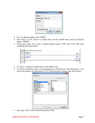
- 4. SHIVAM SINGH (+91-9971457422) Page | 3 ’éĘ Give it a physical address like ŌĆ£P0000ŌĆØ ’éĘ Now select a ŌĆ£CoilŌĆØ, place it at output side, provide variable name and give physical address ŌĆ£P0020ŌĆØ. ’éĘ Using above steps, letŌĆÖs create a simple program using a ŌĆ£NOŌĆØ and ŌĆ£CoilŌĆØ that looks something like shown below. ’éĘ To write a ŌĆ£commentŌĆØ double click on the leftmost cell. ’éĘ To tell the softmaster where your programming is finished put ŌĆ£End StatementŌĆØ at the end of the program. For that click on ŌĆ£F10ŌĆØ that will open a window like shown below. ’éĘ Now type ŌĆ£ENDŌĆØ at the instruction and then ŌĆ£OKŌĆØ.
- 5. SHIVAM SINGH (+91-9971457422) Page | 4 ’éĘ Now move to ŌĆ£ToolsŌĆØ and select ŌĆ£Start SimulatorŌĆØ to check your program. ’éĘ We normally use ŌĆ£SimulatorŌĆØ when we are not working online i.e. with actual PLC and want to check our program. ’éĘ Similarly we can use ŌĆ£NCŌĆØ also, that works exactly opposite to ŌĆ£NOŌĆØ. HOW TO CREATE LOGIC GATES USING LADDER LOGIC ’éĘ Below shown are the logics for all the logic gates.
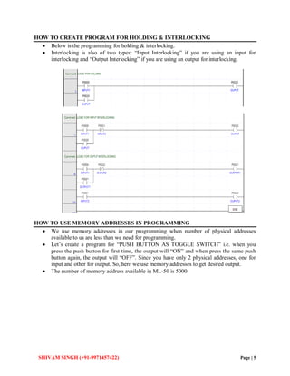
- 6. SHIVAM SINGH (+91-9971457422) Page | 5 HOW TO CREATE PROGRAM FOR HOLDING & INTERLOCKING ’éĘ Below is the programming for holding & interlocking. ’éĘ Interlocking is also of two types: ŌĆ£Input InterlockingŌĆØ if you are using an input for interlocking and ŌĆ£Output InterlockingŌĆØ if you are using an output for interlocking. HOW TO USE MEMORY ADDRESSES IN PROGRAMMING ’éĘ We use memory addresses in our programming when number of physical addresses available to us are less than we need for programming. ’éĘ LetŌĆÖs create a program for ŌĆ£PUSH BUTTON AS TOGGLE SWITCHŌĆØ i.e. when you press the push button for first time, the output will ŌĆ£ONŌĆØ and when press the same push button again, the output will ŌĆ£OFFŌĆØ. Since you have only 2 physical addresses, one for input and other for output. So, here we use memory addresses to get desired output. ’éĘ The number of memory address available in ML-50 is 5000.
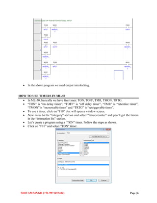
- 7. SHIVAM SINGH (+91-9971457422) Page | 6 ’éĘ In the above program we used output interlocking. HOW TO USE TIMERS IN ML-50 ’éĘ In ML-50, basically we have five timer: TON, TOFF, TMR, TMON, TRTG. ’éĘ ŌĆ£TONŌĆØ is ŌĆ£on delay timerŌĆØ, ŌĆ£TOFFŌĆØ is ŌĆ£off delay timerŌĆØ, ŌĆ£TMRŌĆØ is ŌĆ£retentive timerŌĆØ, ŌĆ£TMONŌĆØ is ŌĆ£monostable timerŌĆØ and ŌĆ£TRTGŌĆØ is ŌĆ£retriggerable timerŌĆØ. ’éĘ To use a timer, click on ŌĆ£F10ŌĆØ that will open a window screen. ’éĘ Now move to the ŌĆ£categoryŌĆØ section and select ŌĆ£timer/counterŌĆØ and youŌĆÖll get the timers in the ŌĆ£instruction listŌĆØ section. ’éĘ LetŌĆÖs create a program using a ŌĆ£TONŌĆØ timer. Follow the steps as shown. ’éĘ Click on ŌĆ£F10ŌĆØ and select ŌĆ£TONŌĆØ timer.
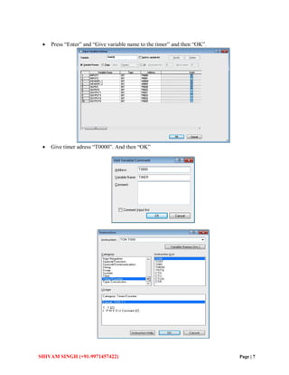
- 8. SHIVAM SINGH (+91-9971457422) Page | 7 ’éĘ Press ŌĆ£EnterŌĆØ and ŌĆ£Give variable name to the timerŌĆØ and then ŌĆ£OKŌĆØ. ’éĘ Give timer adress ŌĆ£T0000ŌĆØ. And then ŌĆ£OKŌĆØ
- 9. SHIVAM SINGH (+91-9971457422) Page | 8 ’éĘ Now give the timing value of timer and remember in ML-50 timer understands only in ŌĆ£msŌĆØ and 10ms=1s and then click on ŌĆ£OKŌĆØ. ’éĘ Note: There are 255 timers in ML-50. ’éĘ Your program will something look like as shown below: ’éĘ In same manner as shown above, one can create program for any timer. ’éĘ Remember one thing that while using ŌĆ£TONŌĆØ timer one must provide holding to its input so that it work properly. ’éĘ Now create program for using ŌĆ£TONŌĆØ Timer as ŌĆ£TOFFŌĆØ
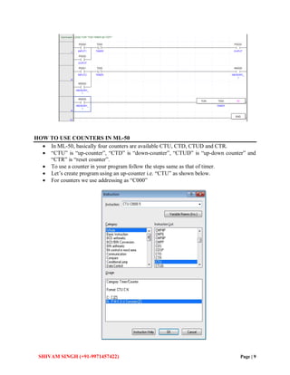
- 10. SHIVAM SINGH (+91-9971457422) Page | 9 HOW TO USE COUNTERS IN ML-50 ’éĘ In ML-50, basically four counters are available CTU, CTD, CTUD and CTR. ’éĘ ŌĆ£CTUŌĆØ is ŌĆ£up-counterŌĆØ, ŌĆ£CTDŌĆØ is ŌĆ£down-counterŌĆØ, ŌĆ£CTUDŌĆØ is ŌĆ£up-down counterŌĆØ and ŌĆ£CTRŌĆØ is ŌĆ£reset counterŌĆØ. ’éĘ To use a counter in your program follow the steps same as that of timer. ’éĘ LetŌĆÖs create program using an up-counter i.e. ŌĆ£CTUŌĆØ as shown below. ’éĘ For counters we use addressing as ŌĆ£C000ŌĆØ
- 11. SHIVAM SINGH (+91-9971457422) Page | 10 ’éĘ Your program will look something like shown below: ’éĘ In same manner one can use any counter. HOW TO USE COMPARE BLOCKS ’éĘ To use compare blocks like less than, greater than, less than equal to, greater than equal to etc. go to ŌĆ£F10ŌĆØ and follow steps as shown. ’éĘ As you can see in the instruction column type the sign for comparison like <=, >=, =, >, < etc. follow by the address you want to compare like here is the address for timer ŌĆ£T000ŌĆØ and then enter its value to compare. ’éĘ LetŌĆÖs create program using compare blocks to make process continuous using single timer.
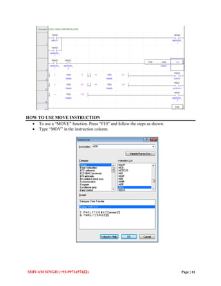
- 12. SHIVAM SINGH (+91-9971457422) Page | 11 HOW TO USE MOVE INSTRUCTION ’éĘ To use a ŌĆ£MOVEŌĆØ function. Press ŌĆ£F10ŌĆØ and follow the steps as shown: ’éĘ Type ŌĆ£MOVŌĆØ in the instruction column.
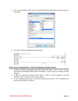
- 13. SHIVAM SINGH (+91-9971457422) Page | 12 ’éĘ Now give the address of the source data location and then destination where one wants to move data. ’éĘ Your logic will be something like shown below: HOW TO USE ARITHMETIC AND CONVERSION INSTRUCTIONS ’éĘ In ML-50, arithmetic instructions like ADD, SUB, DIV, MUL is used if you are working with Integer and RADD, RSUB, RDIV and RMUL is used if you are working with real integers. ’éĘ In ML-50, conversion instruction like ŌĆ£I2RŌĆØ is used to convert integer to real and similarly ŌĆ£ R2IŌĆØ is used to convert real to integer. ’éĘ To use arithmetic instructions or conversion instructions, click on ŌĆ£F10ŌĆØ and follow the instructions and follow as shown:
- 14. SHIVAM SINGH (+91-9971457422) Page | 13 ’éĘ Here ŌĆ£M000ŌĆØ and ŌĆ£M001ŌĆØ are the addresses of the data to be added and ŌĆ£M003ŌĆØ is the address of the location where the added data is going to be saved. Your program will look something like as shown below: ’éĘ Now, letŌĆÖs create a program for scaling using arithmetic instructions and conversion instructions. The formula for Scaling is Y={(X-Xmin)(Ymax-Ymin)/(Xmax-Xmin)}+Ymin Where Y is final output X is value coming from field Ymax and Ymin is values provided by the client Xmax and Xmin is default values set through softmaster
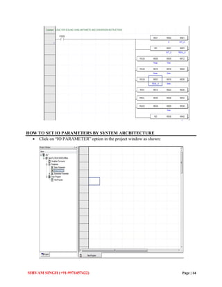
- 15. SHIVAM SINGH (+91-9971457422) Page | 14 HOW TO SET IO PARAMETERS BY SYSTEM ARCHITECTURE ’éĘ Click on ŌĆ£IO PARAMETERŌĆØ option in the project window as shown:
- 16. SHIVAM SINGH (+91-9971457422) Page | 15 ’éĘ Now set the modules in I/O parameter setting as shown ’éĘ Click on the slot ŌĆ£0mainŌĆØ and Select PLC you are working with. ’éĘ Click on the slot 1 or slot 2 and select your DI or DO module accordingly.
- 17. SHIVAM SINGH (+91-9971457422) Page | 16 ’éĘ Click on the slot 3 or slot 4 and select your AI or AO module accordingly. ’éĘ Also select the communication module serial or ethernet if you are using it. ’éĘ Select AI Module and click on ŌĆ£DETAILSŌĆØ. Set the parameters as shown.
- 18. SHIVAM SINGH (+91-9971457422) Page | 17 ’éĘ Now, select AO module and click on ŌĆ£DETAILSŌĆØ. Set the parameters as shown ’éĘ Click ŌĆ£OKŌĆØ and then ŌĆ£YESŌĆØ to register global variables as shown below. ’éĘ Remember to set I/O parameters according to your system architecture. HOW TO CREATE MANUAL LOGIC . ’éĘ To create a manual logic always remember to use memory addresses ŌĆ£M0000ŌĆØ if you are working with HMI and word addresses ŌĆ£D0000ŌĆØ if you are working with SCADA. ’éĘ Below is the program for manual logic for DI/DO.
- 19. SHIVAM SINGH (+91-9971457422) Page | 18 ’éĘ Manual logic for AI/AO with scaling. ’éĘ As in AI and AO, addresses are already assigned by the softmaster, we only need to select them.
- 20. SHIVAM SINGH (+91-9971457422) Page | 19