Ladder system programming using mobile app
- 1. Programming with Ladder System Using Mobile APP (Extra Material) Industrial Automation Discipline for Electromechanical Technical Course Professor MATHEUS Orlandini Domiciano 1 The Ladder Programming System is a system that encompasses the basic knowledge of binary logic systems, logic gates, electric motor controls and even more. The system that we are using in our course is the one available for Clic-02 WEG, which is a PLC model manufactured by WEG and that makes programming software available for free. Unfortunately, there is no compatible the mobile phone APP and the Clic-02 WEG. However, to get around the situation because some students donŌĆÖt have a computer to use the software, I developed this small tutorial for an APP that has limited resources, but that can help so much during the course. Download the APP: ’éĘ PLC Ladder Logic Simulator Desenvolvido por ŌĆ£raincontinuesŌĆØ The first task to understand is the APP's premises. Let's see: 1. The APP works similarly to the Ladder of Clic02-WEG, however with several limitations. 2. It works as a kind of spreadsheet, with rows, columns and cells, but the separations between them are not visible. 3. The programming system has its linear logic horizontally, and it reads each line sequentially, so it cannot be expected that it will execute line 5 before line 1. 4. The cells in the last column on the right are always intended for completion, either with an output coil, a memory coil, a timer or a counter. 5. The coil is the last element of a programming line. There can be nothing after it. Therefore, the logic of two coils in series in Ladder programming does not exist. 6. There should not be two coils with the same name, although this APP will accept this directive, it should not be used, as the real programming Ladder system does not understand that the coils have the same address.
- 2. Programming with Ladder System Using Mobile APP (Extra Material) Industrial Automation Discipline for Electromechanical Technical Course Professor MATHEUS Orlandini Domiciano 2 7. Basic graphic symbols of the programming system are the same: 8. When providing for a machine shutdown contact, care must be taken to place a NO on the Ladder instead of an NC, as, by Standard, the physical external button will be an NC, therefore, it must be understood that the input of the PLC will receive a continuous ŌĆ£1ŌĆØ signal coming from the button. 9. The Outputs: 9.1. Coil: refers to a coil, as if it were a physical output from the PLC. Corresponds to the ŌĆ£QŌĆØ type output on the ladder. 9.2. Memory: refers to a memory output to be used as an auxiliary resource. 9.3. Negative Coil: refers to a coil too, but in a state contrary to the previous item. 9.4. Latch: refers to a type of memory output, however with locking, once powered it cannot be turned off, unless a Reset is activated. It is a good feature to use with pushbutton. 9.5. Unlatch: performs the opposite function that the Latch memory would be performing. Serves as Reset for the Latch function. 9.6. Timer ON: Timer function, referring to Ladder would be mode 1. The moment this timer receives signal 1 from some input, this signal being continuous, it starts counting the time until it reaches the established time value, and, upon reaching this value, it sends signal 1 at the output. If the timer input signal stops, the timer stops performing the task and resets. 9.7. Timer OFF: Timer function, referring to Ladder would be mode 3, however at the beginning of the simulation, the function is activated (perhaps due to a failure in the development of the APP), but works in the opposite way to Timer On. 9.8. When this timer receives a continuous signal 1 from some input, it activates signal 1 at the output. When he stops receiving signal 1 at the entrance, it will start
- 3. Programming with Ladder System Using Mobile APP (Extra Material) Industrial Automation Discipline for Electromechanical Technical Course Professor MATHEUS Orlandini Domiciano 3 counting the time and, when reaching the established time value, it will turn off signal 1 of the output. 9.9. Counter UP: This counter counts up. Referring to Ladder would be mode 2. 9.10. Counter DOWN: This counter counts down. Referring to Ladder like mode 2. 9.11. Reset: Used only to reset the counters. 10. In this APP, the timers do not have a reset feature, because when they stop receiving power (or ŌĆ£1ŌĆØ signal), they simply stop the time and reset. 11. To this software work, itŌĆÖs necessary to number (or address) each function inserted by clicking on Address with finger just above the function. If this is not done, the APP will simply crash and close. It is important to do this with each insertion, because if you leave it to the end the work will be much greater. Let's go to the practical part: After installing the APP on your android smartphone, open it: Step 2: Click on ŌĆ£BlankŌĆØ Step 1: Click ŌĆ£+ŌĆØ
- 4. Programming with Ladder System Using Mobile APP (Extra Material) Industrial Automation Discipline for Electromechanical Technical Course Professor MATHEUS Orlandini Domiciano 4 12. Although you can name and prepare several projects, the APP does not generate any files. The schedules will be saved within the APP but cannot be shared or sent to anyone else. Important information: after making the programming and to send it for correction, you must take a Printscreen (as many as needed) from your smartphone, because the APP does not generate files. Exercises Exercise 2 (reference to the original material): Ladder programming for Lamps: L1 and L2. Step 1: A push button S1 (pushbutton) should light the lamp L1, however it will remain connected by a seal contact of L1. Step 2: When a second push button S2 (pushbutton) lights the L2 lamp, the L1 lamp will turn off. L2 must remain connected with L2 seal contact. Step 3: A third push button S3 (pushbutton) will turn everything off at the same time. Observing, in this case we will use an NC in the Ladder, but normally we use an NA. Step 3: Name the project Step 4: Window ready for programming.
- 5. Programming with Ladder System Using Mobile APP (Extra Material) Industrial Automation Discipline for Electromechanical Technical Course Professor MATHEUS Orlandini Domiciano 5 Resolution in the APP Step 1 (click with your finger): In the red square. Step 2 (click with your finger): Normal Open contact. Step 3 (click with your finger): About the function you just entered and then click Address. Result: Input function inserted with address. Step 4 (click with your finger): ŌĆ£TellŌĆØ the APP what the type of entry is. In this case, if you chose Output, it would link any existing output. Step 5 (click with your finger): At the exit and select ŌĆ£CoilŌĆØ, which is like a physical coil in the PLC.
- 6. Programming with Ladder System Using Mobile APP (Extra Material) Industrial Automation Discipline for Electromechanical Technical Course Professor MATHEUS Orlandini Domiciano 6 Thus, with this basic information it is already possible to do the exercise until the end and then do the simulation. Let's see: Step 6 (click with your finger): About the function you just entered and then click Address. Step 7 (click with your finger): Inform the APP if the output is a coil or a memory. In this case it is a coil. Then enter the exit number.
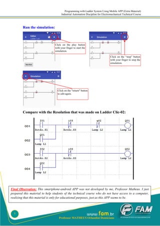
- 7. Programming with Ladder System Using Mobile APP (Extra Material) Industrial Automation Discipline for Electromechanical Technical Course Professor MATHEUS Orlandini Domiciano 7 Run the simulation: Compare with the Resolution that was made on Ladder Clic-02: Click on the play button with your finger to start the simulation. Click on the ŌĆ£stopŌĆØ button with your finger to stop the simulation. Click on the "return" button to edit again. Final Observation: This smartphone-android APP was not developed by me, Professor Matheus. I just prepared this material to help students of the technical course who do not have access to a computer, realizing that this material is only for educational purposes, just as this APP seems to be.


