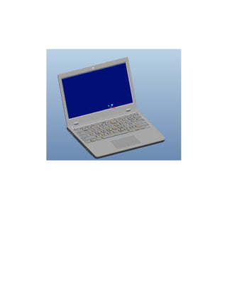
Laptop modelling in pro engineering
- 1. PROJECT REPORT LAPTOP (TOTAL 11 PARTS) NAME: MAFAZ AHMED REG NO: 1882-BSEE/FET/F-12
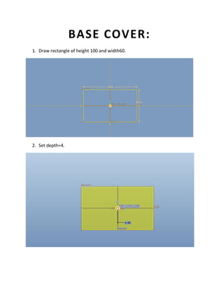
- 3. BASE COVER: 1. Draw rectangle of height 100 and width60. 2. Set depth=4.
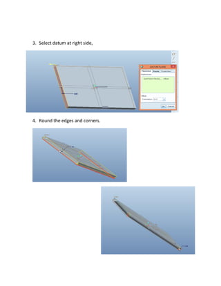
- 4. 3. Select datum at right side, 4. Round the edges and corners.
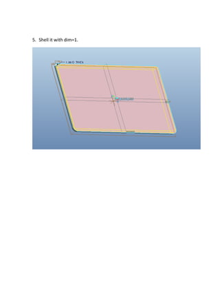
- 5. 5. Shell it with dim=1.
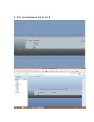
- 6. 6. Draw following drawing and pattern it.
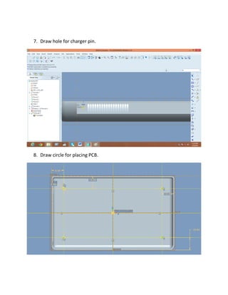
- 7. 7. Draw hole for charger pin. 8. Draw circle for placing PCB.
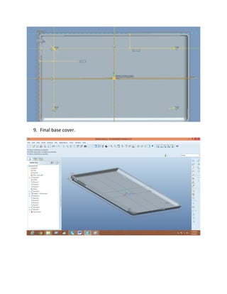
- 8. 9. Final base cover.
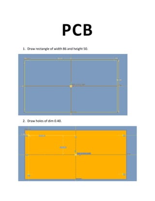
- 9. PCB 1. Draw rectangle of width 86 and height 50. 2. Draw holes of dim 0.40.
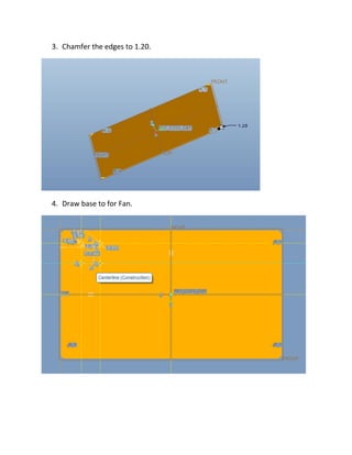
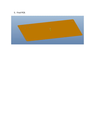
- 10. 3. Chamfer the edges to 1.20. 4. Draw base to for Fan.
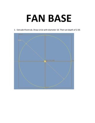
- 11. 5. Final PCB.
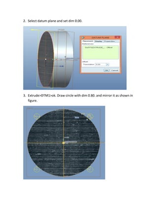
- 12. FAN BASE 1. Extrude>front>ok. Draw circle with diameter 10. Then set depth of 2.50.
- 13. 2. Select datum plane and set dim 0.00. 3. Extrude>DTM1>ok. Draw circle with dim 0.80. and mirror it as shown in figure.
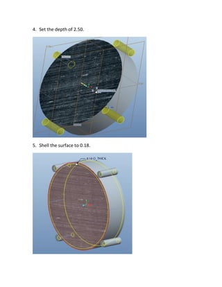
- 14. 4. Set the depth of 2.50. 5. Shell the surface to 0.18.
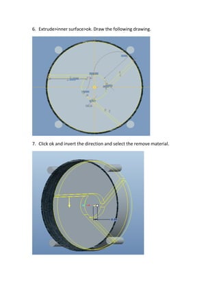
- 15. 6. Extrude>inner surface>ok. Draw the following drawing. 7. Click ok and invert the direction and select the remove material.
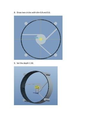
- 16. 8. Draw two circles with dim 0.8 and 0.6. 9. Set the depth 1.50.
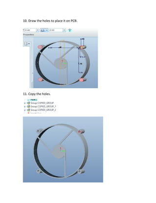
- 17. 10. Draw the holes to place it on PCB. 11. Copy the holes.
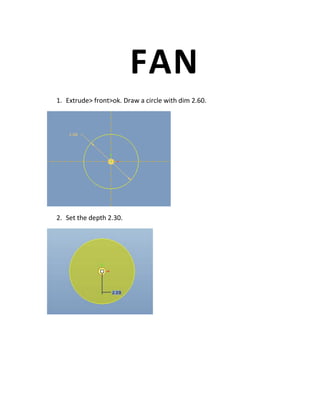
- 18. FAN 1. Extrude> front>ok. Draw a circle with dim 2.60. 2. Set the depth 2.30.
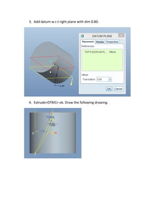
- 19. 3. Add datum w.r.t right plane with dim 0.80. 4. Extrude>DTM1> ok. Draw the following drawing.
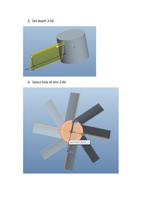
- 20. 5. Set depth 3.50. 6. Select hole of dim 2.00.
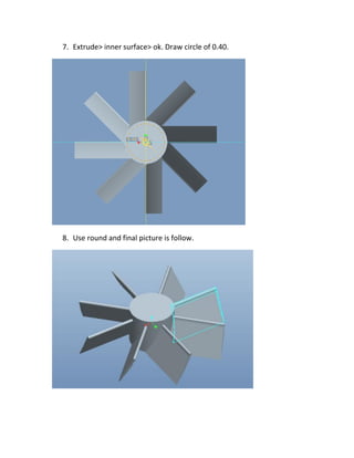
- 21. 7. Extrude> inner surface> ok. Draw circle of 0.40. 8. Use round and final picture is follow.
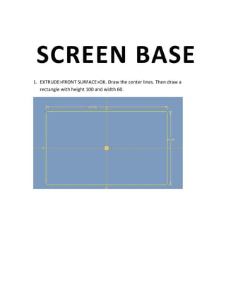
- 22. SCREEN BASE 1. EXTRUDE>FRONT SURFACE>OK. Draw the center lines. Then draw a rectangle with height 100 and width 60.
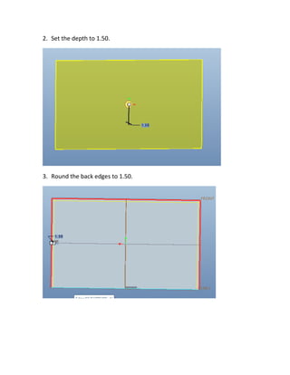
- 23. 2. Set the depth to 1.50. 3. Round the back edges to 1.50.
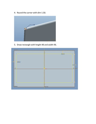
- 24. 4. Round the corner with dim 1.50. 5. Draw rectangle with height 48 and width 96.
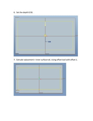
- 25. 6. Set the depth 0.50. 7. Extrude >placement > inner surface>ok. Using offset tool with offset 1.
- 26. 8. Apply round to corners and edges. 9. Draw small rectangle in base to place it with laptop.
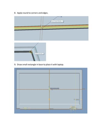
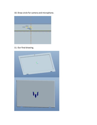
- 27. 10. Draw circle for camera and microphone. 11. Our final drawing.
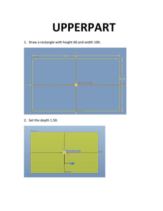
- 28. UPPERPART 1. Draw a rectangle with height 60 and width 100. 2. Set the depth 1.50.
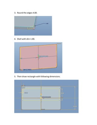
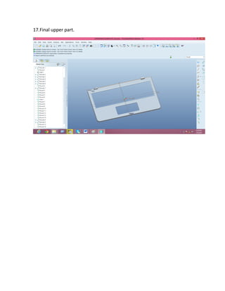
- 29. 3. Round the edges 4.00. 4. Shell with dim 1.00. 5. Then draw rectangle with following dimensions.
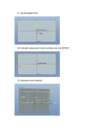
- 30. 9. Set the depth 0.30. 10. Extrude >placement >inner surface> ok. Use OFFSET. 11. Remove inner material.
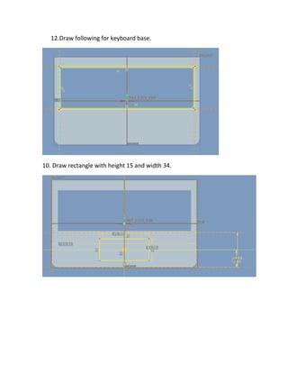
- 31. 12.Draw following for keyboard base. 10. Draw rectangle with height 15 and width 34.
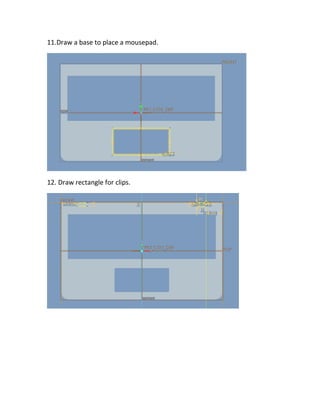
- 32. 11.Draw a base to place a mousepad. 12. Draw rectangle for clips.
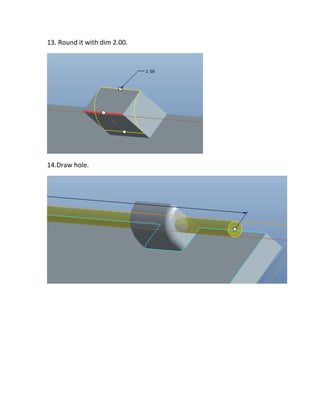
- 33. 13. Round it with dim 2.00. 14.Draw hole.
- 34. 15. Draw a circle with dim 2.50. Power button will be place here. 16. Apply round feature on corners and edges.
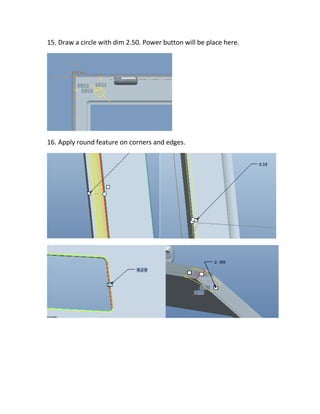
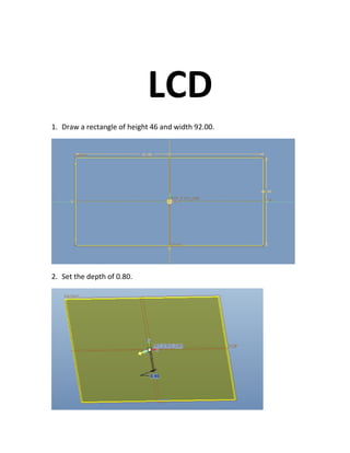
- 36. LCD 1. Draw a rectangle of height 46 and width 92.00. 2. Set the depth of 0.80.
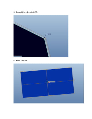
- 37. 3. Round the edges to 0.50. 4. Final picture.
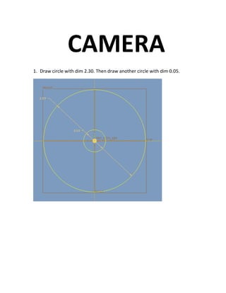
- 38. CAMERA 1. Draw circle with dim 2.30. Then draw another circle with dim 0.05.
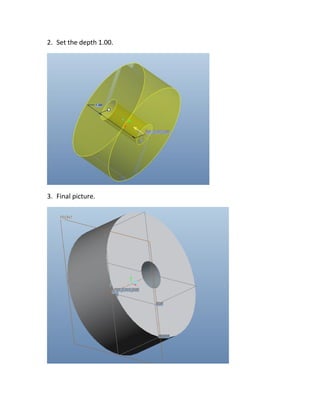
- 39. 2. Set the depth 1.00. 3. Final picture.
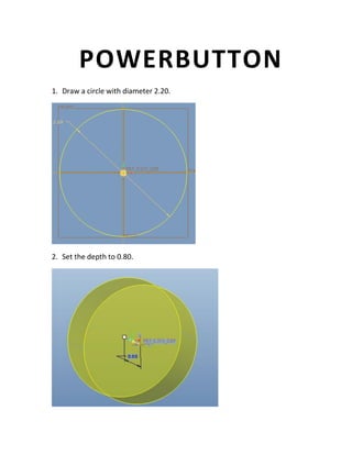
- 40. POWERBUTTON 1. Draw a circle with diameter 2.20. 2. Set the depth to 0.80.
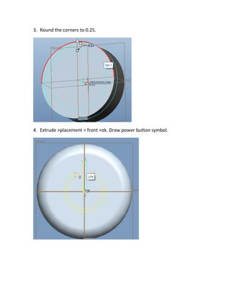
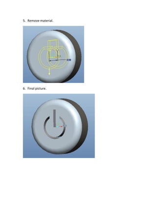
- 41. 3. Round the corners to 0.25. 4. Extrude >placement > front >ok. Draw power button symbol.
- 42. 5. Remove material. 6. Final picture.
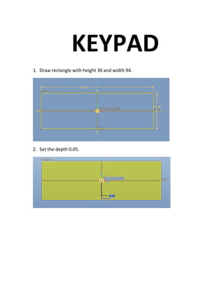
- 43. KEYPAD 1. Draw rectangle with height 30 and width 94. 2. Set the depth 0.05.
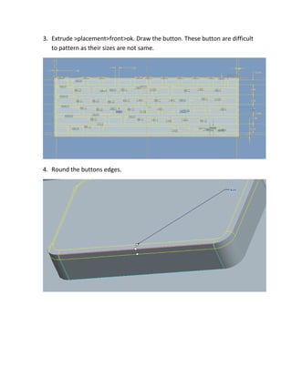
- 44. 3. Extrude >placement>front>ok. Draw the button. These button are difficult to pattern as their sizes are not same. 4. Round the buttons edges.
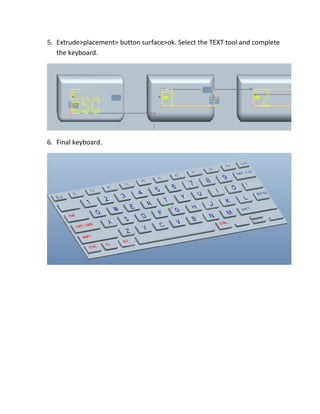
- 45. 5. Extrude>placement> button surface>ok. Select the TEXT tool and complete the keyboard. 6. Final keyboard.
- 46. MOUSEPAD 1. Draw a rectangle of height 17 and width36. 2. Set the depth to 0.10.
- 47. 3. Extrude >placement >define > front>ok. Use OFFSET tool to draw the following rectangle. 7. Set the depth to 0.05.
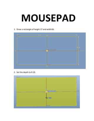
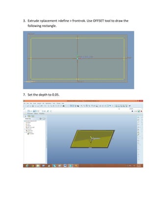
- 48. 8. Draw two buttons on mouse pad. 9. Remove the inner material to 1.00.
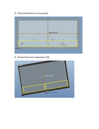
- 49. 10.Round the edges to dim1.00. 11. Final picture of mouse pad.


