Lectures-CLL361.pdf
- 1. CLL 361 Instrumentation & Automation Department of Chemical Engineering Source: ║¦║¦▀ús prepared by Dr. M.A. Shaik
- 2. Outline ? Introduction ? Importance of Process Control ? Control Theory Basics ? Control Algorithms and Tuning ? Components of Control Loops ? Instrumentation
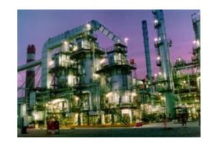
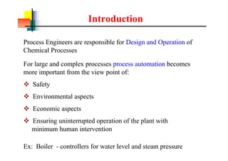
- 7. Introduction Process Engineers are responsible for Design and Operation of Chemical Processes Ex: Boiler - controllers for water level and steam pressure For large and complex processes process automation becomes more important from the view point of: v Safety v Environmental aspects v Economic aspects v Ensuring uninterrupted operation of the plant with minimum human intervention
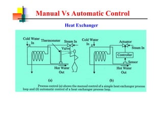
- 9. Manual Vs Automatic Control Heat Exchanger
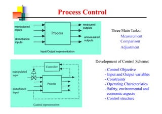
- 10. Process Control Three Main Tasks: Measurement Comparison Adjustment - Control Objective - Input and Output variables - Constraints - Operating Characteristics - Safety, environmental and economic aspects - Control structure Development of Control Scheme:
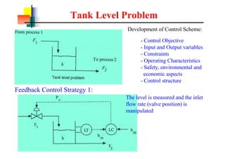
- 11. Tank Level Problem Feedback Control Strategy 1: The level is measured and the inlet flow rate (valve position) is manipulated - Control Objective - Input and Output variables - Constraints - Operating Characteristics - Safety, environmental and economic aspects - Control structure Development of Control Scheme:
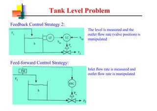
- 12. Tank Level Problem Feedback Control Strategy 2: The level is measured and the outlet flow rate (valve position) is manipulated Feed-forward Control Strategy: Inlet flow rate is measured and outlet flow rate is manipulated
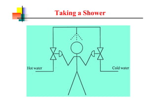
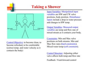
- 13. Taking a Shower Input Variables: Manipulated input variables are HW and CW valve positions, body position. Disturbance inputs include a drop in water pressure and changes to HW temp. Control Objective: to become clean, to become refreshed, to be comfortable (correct temp. and water velocity as it contacts the body) Output Variables: Measured output variables are temp and flow rate of mixed stream as it contacts your body. Constraints: Min and Max valve positions on both streams. Min and Max flow rates (hard constraints). Mixed water temp (soft constraint). Control Structure: Adjusting either valve affects both temp and flow rate Feedback / Feed-forward control
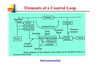
- 15. Elements of a Control Loop Instrumentation
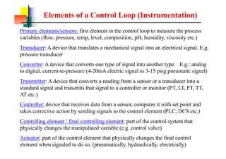
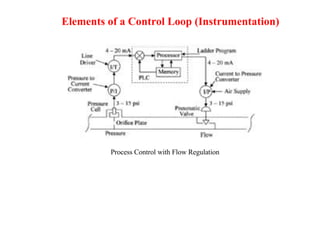
- 16. Elements of a Control Loop (Instrumentation) Primary elements/sensors: first element in the control loop to measure the process variables (flow, pressure, temp, level, composition, pH, humidity, viscosity etc.) Transducer: A device that translates a mechanical signal into an electrical signal. E.g. pressure transducer Converter: A device that converts one type of signal into another type. E.g.: analog to digital, current-to-pressure (4-20mA electric signal to 3-15 psig pneumatic signal) Transmitter: A device that converts a reading from a sensor or a transducer into a standard signal and transmits that signal to a controller or monitor (PT, LT, FT, TT, AT etc.) Controller: device that receives data from a sensor, compares it with set point and takes corrective action by sending signals to the control element (PLC, DCS etc.) Controlling element / final controlling element: part of the control system that physically changes the manipulated variable (e.g. control valve) Actuator: part of the control element that physically changes the final control element when signaled to do so. (pneumatically, hydraulically, electrically)
- 17. Elements of a Control Loop (Instrumentation) Process Control with Flow Regulation
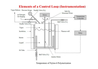
- 18. Elements of a Control Loop (Instrumentation) Temperature of Nylon-6 Polymerization
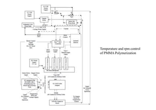
- 19. Temperature and rpm control of PMMA Polymerization
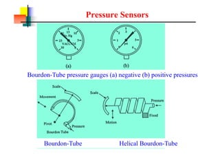
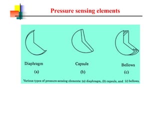
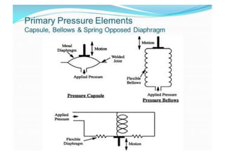
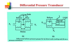
- 20. Pressure Sensors Bourdon-Tube pressure gauges (a) negative (b) positive pressures Bourdon-Tube Helical Bourdon-Tube
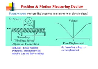
- 24. Position & Motion Measuring Devices (a) LVDT: Linear Variable Differential Transformer with movable core and three windings (b) Secondary voltage vs core displacement Potentiometers convert displacement in a sensor to an electric signal
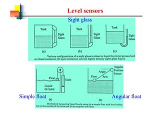
- 25. Level sensors Sight glass Simple float Angular float
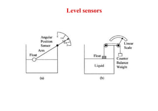
- 26. Level sensors
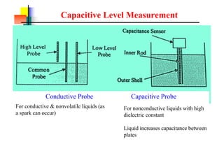
- 27. Capacitive Level Measurement Conductive Probe Capacitive Probe For conductive & nonvolatile liquids (as a spark can occur) For nonconductive liquids with high dielectric constant Liquid increases capacitance between plates
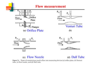
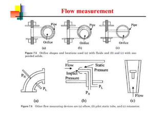
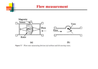
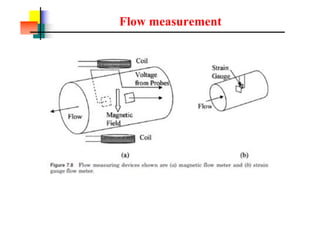
- 29. Flow measurement Orifice Plate Venturi Tube Flow Nozzle Dall Tube
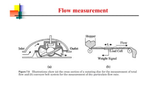
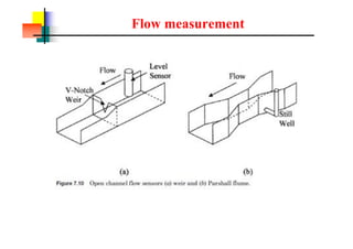
- 30. Flow measurement
- 31. Flow measurement
- 32. Flow measurement
- 33. Flow measurement
- 34. Flow measurement
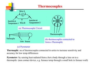
- 37. Thermocouples (b) thermocouples connected to form a Thermopile Thermopile: no of thermocouples connected in series to increase sensitivity and accuracy for low temp differences (a) Thermocouple Circuit (c) Pyrometer Pyrometer: by sensing heat radiated from a hot a body through a lens on to a thermopile (non contact device, e.g. furnace temp through a small hole in furnace wall)
- 38. Thermocouples
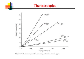
- 39. Thermocouples
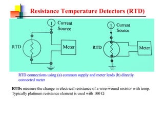
- 40. Resistance Temperature Detectors (RTD) RTDs measure the change in electrical resistance of a wire-wound resistor with temp. Typically platinum resistance element is used with 100 W RTD connections using (a) common supply and meter leads (b) directly connected meter
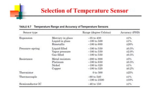
- 41. Selection of Temperature Sensor
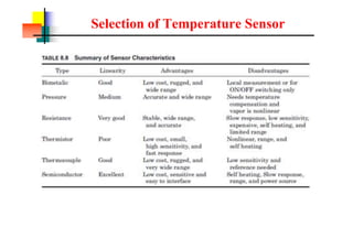
- 42. Selection of Temperature Sensor
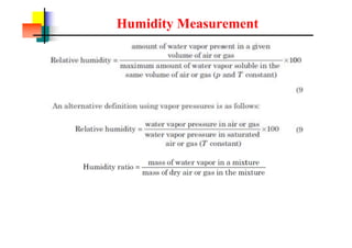
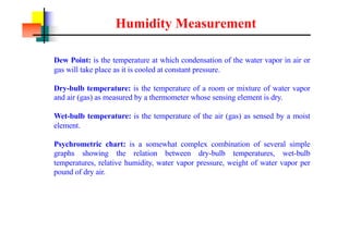
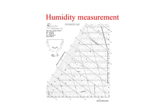
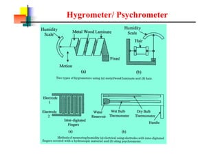
- 44. Humidity Measurement Dew Point: is the temperature at which condensation of the water vapor in air or gas will take place as it is cooled at constant pressure. Dry-bulb temperature: is the temperature of a room or mixture of water vapor and air (gas) as measured by a thermometer whose sensing element is dry. Wet-bulb temperature: is the temperature of the air (gas) as sensed by a moist element. Psychrometric chart: is a somewhat complex combination of several simple graphs showing the relation between dry-bulb temperatures, wet-bulb temperatures, relative humidity, water vapor pressure, weight of water vapor per pound of dry air.
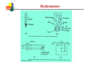
- 47. Hydrometer
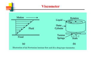
- 48. Viscometer
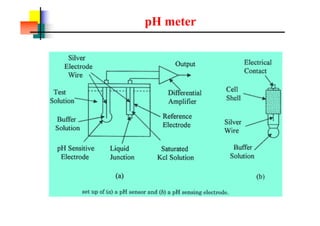
- 49. pH meter
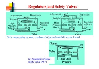
- 50. Regulators and Safety Valves Self-compensating pressure regulators (a) Spring loaded (b) weight loaded (c) Automatic pressure safety valve (PSV)
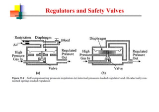
- 51. Regulators and Safety Valves
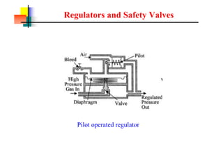
- 52. Regulators and Safety Valves Pilot operated regulator
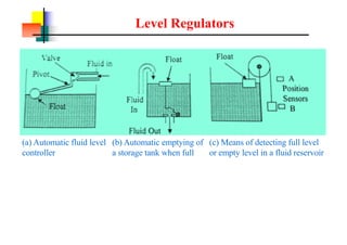
- 53. Level Regulators (a) Automatic fluid level controller (b) Automatic emptying of a storage tank when full (c) Means of detecting full level or empty level in a fluid reservoir
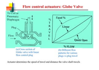
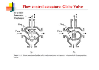
- 54. Flow control actuators: Globe Valve (a) Cross section of Globe valve with linear flow control plug (b) Different flow patterns for various plugs vs plug travel Actuator determines the speed of travel and distance the valve shaft travels
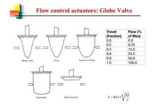
- 55. Flow control actuators: Globe Valve Travel (fraction) Flow (% of Max) 0.0 0.0 0.2 6.25 0.4 12.5 0.6 25.0 0.8 50.0 1.0 100.0
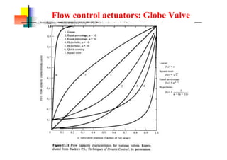
- 56. Flow control actuators: Globe Valve
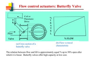
- 57. Flow control actuators: Butterfly Valve (a) Cross section of a butterfly valve (b) Flow vs travel characteristic The relation between flow and lift is approximately equal % up to 50% open after which it is linear. Butterfly valves offer high capacity at low cost.
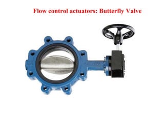
- 58. Flow control actuators: Butterfly Valve
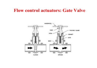
- 59. Flow control actuators: Gate Valve
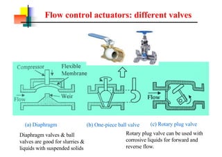
- 60. Flow control actuators: different valves (a) Diaphragm (b) One-piece ball valve (c) Rotary plug valve Rotary plug valve can be used with corrosive liquids for forward and reverse flow. Diaphragm valves & ball valves are good for slurries & liquids with suspended solids
- 61. Flow control actuators: Globe Valve
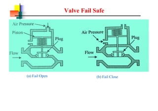
- 62. Valve Fail Safe (a) Fail Open (b) Fail Close
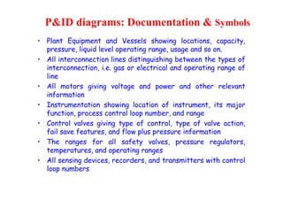
- 63. P&ID diagrams: Documentation & Symbols ? Plant Equipment and Vessels showing locations, capacity, pressure, liquid level operating range, usage and so on. ? All interconnection lines distinguishing between the types of interconnection, i.e. gas or electrical and operating range of line ? All motors giving voltage and power and other relevant information ? Instrumentation showing location of instrument, its major function, process control loop number, and range ? Control valves giving type of control, type of valve action, fail save features, and flow plus pressure information ? The ranges for all safety valves, pressure regulators, temperatures, and operating ranges ? All sensing devices, recorders, and transmitters with control loop numbers
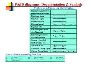
- 64. P&ID diagrams: Documentation & Symbols Symbols for instrument line interconnection Abbreviations for secondary flow lines
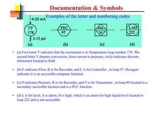
- 65. Documentation & Symbols Examples of the letter and numbering codes ? (a) First letter T indicates that the instrument is in Temperature loop number 178. The second letter Y denotes conversion, from current to pressure, circle indicates discrete instrument located in field. ? (b) F indicates Flow, R is for Recorder, and C is for Controller , in loop 97. Hexagon indicates it is an accessible computer function. ? (c) P indicates Pressure, R is for Recorder, and T is for Transmitter , in loop 89 located in a secondary accessible location and is a PLC function. ? (d) L is for level, A is alarm, H is high, which is an alarm for high liquid level located in loop 222 and is not accessible.
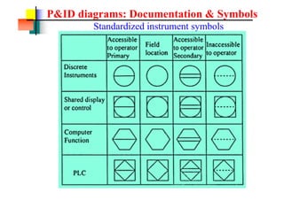
- 66. P&ID diagrams: Documentation & Symbols Standardized instrument symbols
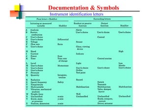
- 67. Documentation & Symbols Instrument identification letters
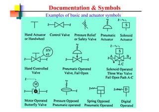
- 68. Documentation & Symbols Examples of basic and actuator symbols
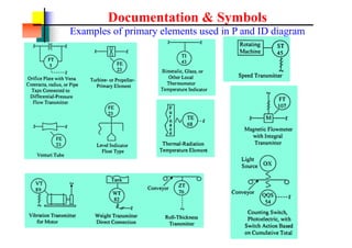
- 69. Documentation & Symbols Examples of primary elements used in P and ID diagram
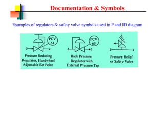
- 70. Documentation & Symbols Examples of regulators & safety valve symbols used in P and ID diagram
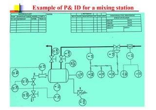
- 71. Example of P& ID for a mixing station
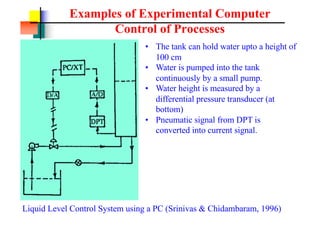
- 72. Examples of Experimental Computer Control of Processes Liquid Level Control System using a PC (Srinivas & Chidambaram, 1996) ? The tank can hold water upto a height of 100 cm ? Water is pumped into the tank continuously by a small pump. ? Water height is measured by a differential pressure transducer (at bottom) ? Pneumatic signal from DPT is converted into current signal.
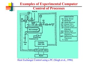
- 73. Examples of Experimental Computer Control of Processes Heat Exchanger Control using a PC (Singh et al., 1996)
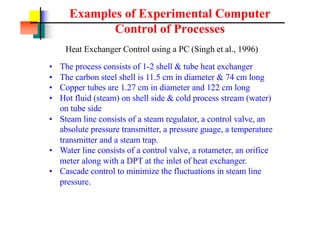
- 74. Examples of Experimental Computer Control of Processes Heat Exchanger Control using a PC (Singh et al., 1996) ? The process consists of 1-2 shell & tube heat exchanger ? The carbon steel shell is 11.5 cm in diameter & 74 cm long ? Copper tubes are 1.27 cm in diameter and 122 cm long ? Hot fluid (steam) on shell side & cold process stream (water) on tube side ? Steam line consists of a steam regulator, a control valve, an absolute pressure transmitter, a pressure guage, a temperature transmitter and a steam trap. ? Water line consists of a control valve, a rotameter, an orifice meter along with a DPT at the inlet of heat exchanger. ? Cascade control to minimize the fluctuations in steam line pressure.
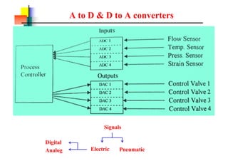
- 75. A to D & D to A converters Signals Pneumatic Electric Digital Analog
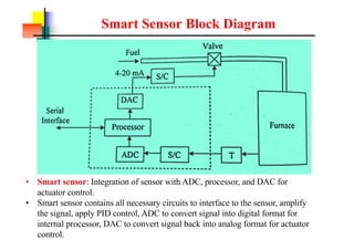
- 76. Smart Sensor Block Diagram ? Smart sensor: Integration of sensor with ADC, processor, and DAC for actuator control. ? Smart sensor contains all necessary circuits to interface to the sensor, amplify the signal, apply PID control, ADC to convert signal into digital format for internal processor, DAC to convert signal back into analog format for actuator control.
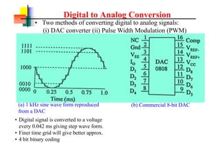
- 77. Digital to Analog Conversion (a) 1 kHz sine wave form reproduced from a DAC (b) Commercial 8-bit DAC ? Two methods of converting digital to analog signals: (i) DAC converter (ii) Pulse Width Modulation (PWM) ? Digital signal is converted to a voltage every 0.042 ms giving step wave form. ? Finer time grid will give better approx. ? 4 bit binary coding
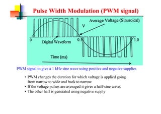
- 78. Pulse Width Modulation (PWM signal) PWM signal to give a 1 kHz sine wave using positive and negative supplies ? PWM changes the duration for which voltage is applied going from narrow to wide and back to narrow. ? If the voltage pulses are averaged it gives a half-sine wave. ? The other half is generated using negative supply
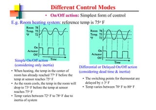
- 79. Different Control Modes ? On/Off action: Simplest form of control E.g. Room heating system: reference temp is 75o F Simple On/Off action (considering only inertia) ? When heating, the temp in the center of room has already reached 77o F before the temp at sensor reaches 75o F ? As the room cools, the temp in the room will drop to 73o F before the temp at sensor reaches 75o F ? Temp varies between 72o F to 78o F due to inertia of system Differential or Delayed On/Off action (considering dead time & inertia) ? The switching points for thermostat are delayed by í└ 3o F ? Temp varies between 70o F to 80o F
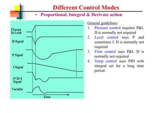
- 80. Different Control Modes ? Proportional, Integral & Derivate action General guidelines: 1. Pressure control requires P&I. D is normally not required 2. Level control uses P and sometimes I. D is normally not required 3. Flow control uses P&I. D is normally not required 4. Temp control uses PID with integral set for a long time period.
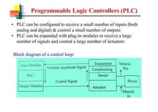
- 81. Programmable Logic Controllers (PLC) ? PLC can be configured to receive a small number of inputs (both analog and digital) & control a small number of outputs ? PLC can be expanded with plug-in modules to receive a large number of signals and control a large number of actuators Block diagram of a control loop:
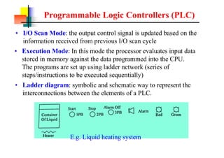
- 82. Programmable Logic Controllers (PLC) ? I/O Scan Mode: the output control signal is updated based on the information received from previous I/O scan cycle ? Execution Mode: In this mode the processor evaluates input data stored in memory against the data programmed into the CPU. The programs are set up using ladder network (series of steps/instructions to be executed sequentially) ? Ladder diagram: symbolic and schematic way to represent the interconnections between the elements of a PLC. E.g. Liquid heating system
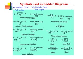
- 83. Symbols used in Ladder Diagrams Push to open Push to close NO: Normally Open NC: Normally Close Position
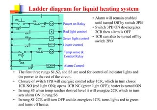
- 84. Ladder diagram for liquid heating system ? The first three rungs S1,S2, and S3 are used for control of indicator lights and the power to the rest of the circuit. ? Closure of switch 1PB will energize control relay 1CR, which in turn closes 1CR NO (red light ON); opens 1CR NC (green light OFF); heater is turned ON ? In rung S5 when temp reaches desired level it will energize 2CR which in turn sets alarm ON in rung S6 ? In rung S1 2CR will turn OFF and de-energizes 1CR, turns lights red to green and turns off heater. ? Alarm will remain enabled until turned Off by switch 3PB ? Switch 3PB ON de-energizes 2CR then alarm is OFF ? 1CR can also be turned off by switch 2PB Power on Relay Red light control Green light control Heater control Temp sense & Control Relay Alarm Control