lec-voltsandcurrent (2).ppt
- 1. Intro to Electric Circuits GLAS wiring
- 2. Electric Circuits • Electricity: The flow of electrons. (Mobile particles, carrying charge) • Circuit: A path for electrons to flow in http://chem-mgriep2.unl.edu/Courses/AnimatedAtoms.html
- 3. Voltage, current, and resistance • The flow of electrons is like the flow of water • Driven by pressure (voltage) • Pressure causes flow (current) • The relationship between pressure and flow is set by the obstacles (resistance) in the flow path • For the flow to do useful work (have power), both pressure and flow must be present ga.water.usgs.gov/edu/hyhowworks.html Hydroelectric Dam
- 4. Circuit functions In general, circuits can be thought of as combinations of: • Power Sources (battery, generator) • Loads (where power is used) (lamps, speakers, motors) • Conduction Paths (wires) • Controls (switches & knobs) • Indicators (meters, flashing lights, buzzers)
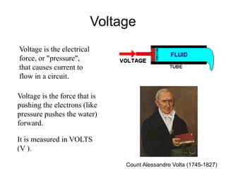
- 5. Voltage Voltage is the electrical force, or "pressure", that causes current to flow in a circuit. It is measured in VOLTS (V ). Voltage is the force that is pushing the electrons (like pressure pushes the water) forward. Count Alessandro Volta (1745-1827)
- 6. Current is the movement of electrical charge - the flow of electrons through the electronic circuit. In our analogy, current would be the flow of water moving through the tube (wire). Current is defined to flow from positive to negative voltages Voltage Current Current is measured in AMPERES (AMPS, A or I). Current Andre-Marie Ampere (1775-1836)
- 7. Conductors, Insulators, and Semiconductors • A conductor is a material (usually a metal such as copper) that allows electric current to pass easily. • This is opposed to an insulator (plastic, glass) which prevents the flow of electricity through it. • Semiconductors have intermediate properties which enable their conduction to be modified and controlled.
- 8. Resistance is anything that causes an opposition to the flow of current in a circuit. Resistance - + Voltage Current Resistance Resistance controls the amount of voltage and current in a circuit. Everything in a circuit has a resistance (even wire). A resistor is a device designed specifically to have a constant resistance. It is measured in OHMS (W). Design and analysis of electronic circuits hinges on thorough understanding of the relationships between voltage, current, and resistance.
- 9. expresses the relationship between current, voltage, and resistance. It was named after the German physicist Georg Simon Ohm (1787-1854). This is one of the most fundamental concepts in electronics. Learn Ohm’s Law. Learn it inside and out! Quantification: Ohm’s Law W
- 10. V is the voltage between two points (measured in volts) I is the current flowing along a path between those two points (measured in amperes) R is the resistance of that path (measured in Ohms) Volts = Amps times Ohms Ohm’s Law
- 11. Voltage (Volts) Current Current (Amps) Load/Resistor (Ohms) Electronic Schematics • Electronic circuits are drawn using schematics which use standard symbols for each type of electronic component V I R + - Circuit Schematic Diode Transistors Capacitor battery symbol resistor symbol
- 12. If in this circuit we observe a current flow of 12 amps (12A) through the resistive load of 1 Ohm (1W), what must the battery voltage be? V = I R V = 12 (Amps) x 1 (Ohm) V = 12 Volts (12V) V ?
- 13. If we knew the battery was supplying 12 volts, how do we predict the current through a resistive load of 1 Ohm? I = 12 (Volts)/ 1 (Ohm) : I = 12 Amps (12A) I = V / R I ?
- 14. If we knew a 10V battery was supplying 5A of current, what must the load (resistance) be? R = 10 (Volts)/ 5 (Amps) : R = 2 Ohm (2 W) R = V / I ? W 5 10V
- 15. • For electrons to flow contiusly, there must be a compete circuit in which electrons return to their source. • Think of it as a circle. The paths may split off here and there but they always rejoin the source eventually. http://www.ibiblio.org/kuphaldt/socratic/output/animation_switch_circuit_fast.gif Electronic circuits Evaporation Condensation
- 16. Series Circuit A series circuit is one with all the loads in a row. Like links in a chain. There is only ONE path for the electricity to flow. If this circuit was a string of light bulbs, and one blew out (became an open circuit), the remaining bulbs would turn off. Circuit components in series experience the same current.
- 17. Parallel Circuit A parallel circuit is one that has two or more paths for the electricity to flow – similar to a fork in a river In other words, the loads are parallel to each other. If the loads in this circuit were light bulbs and one blew out, current would still flow to the others. Circuit components in parallel experience the same voltage.
- 18. Now you are ready for a Demo!
- 19. Ohm’s Law test circuit A V Voltage source Load resistor Current meter (in series with load) Voltage meter (in parallel with load)


