Lesson01
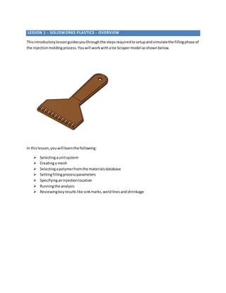
- 1. LESSON 1 - SOLIDWORKS PLASTICS - OVERVIEW Thisintroductorylessonguidesyouthroughthe stepsrequiredtosetupandsimulatethe fillingphase of the injectionmoldingprocess.Youwill workwithaIce Scrapermodel asshownbelow. In thislesson,youwill learnthe following: ÔÉò Selectingaunitsystem ÔÉò Creatinga mesh ÔÉò Selectingapolymerfromthe materialsdatabase ÔÉò Settingfillingprocessparameters ÔÉò Specifyinganinjectionlocation ÔÉò Runningthe analysis ÔÉò Reviewingkeyresults like sinkmarks,weldlinesandshrinkage
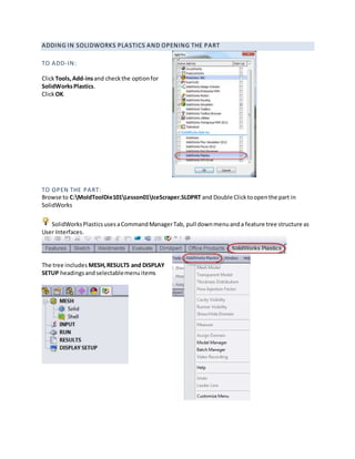
- 2. ADDING IN SOLIDWORKS PLASTICS AND OPENING THE PART TO ADD-IN: ClickTools,Add-insand checkthe optionfor SolidWorksPlastics. ClickOK. TO OPEN THE PART: Browse to C:MoldToolDie101Lesson01IceScraper.SLDPRT and Double Clicktoopenthe part in SolidWorks SolidWorksPlasticsusesaCommandManagerTab, pull downmenuanda feature tree structure as User Interfaces. The tree includes MESH,RESULTS and DISPLAY SETUP headingsand selectablemenuitems
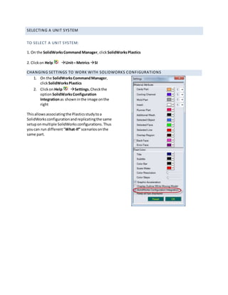
- 3. SELECTING A UNIT SYSTEM TO SELECT A UNIT SYSTEM: 1. On the SolidWorksCommand Manager, clickSolidWorksPlastics 2. Clickon Help Unit– Metrics SI CHANGING SETTINGS TO WORK WITH SOLIDWORKS CONFIGURATIONS 1. On the SolidWorksCommandManager, clickSolidWorksPlastics 2. Clickon Help Settings.Checkthe option SolidWorksConfiguration Integrationas showninthe image onthe right Thisallowsassociatingthe Plasticsstudytoa SolidWorksconfigurationandreplicatingthe same setuponmultiple SolidWorksconfigurations.Thus youcan run different“What-If” scenariosonthe same part.
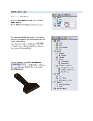
- 4. CREATING THE MESH TO CREATE THE MESH: 1. On the Plastics Feature Tree, Double Click on MESH Shell 2. SelectAuto fromthe popupmenuas shown. The meshingtakesa fewseconds.Assoonasit’s done,the software createsadditional itemsinthe PlasticsFeature Tree. Note the checkmark on the Shell icon inthe studytree indicatingthatthe meshinghas beensuccessfullycompleted. To viewthe Mesh,clickon the MeshModel inthe SolidWorksPlastics CommandManager.To hide the mesh,clickon MeshModel again.
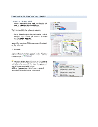
- 5. SELECTING A POLYMER FOR THE ANALYSIS TO SELECT THE POLYMER: 1. On the PlasticsFeature Tree,DoubleClick on INPUT MaterialPolymericon. The PolymerMaterial database appears. 2. From the Polymerlistonthe leftside,clickon the plussignnextto 1 ABS and thencheckthe box 24: BASF/ ABS6003. Material propertiesof thispolymerare displayed on the rightside 3. Click OK A greencheckmark nowappearson the Polymer iconSolidWorks The selectedmaterial isautomaticallyadded to the Favorite Materialslist.Nexttimeyouwant to use the same material,simply RMB onPolymer iconinthe feature tree and selectthe favorite materialfromthe list.
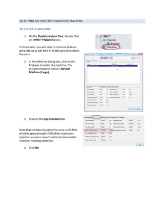
- 6. SELECTING AN INJECTION MOLDING MACHINE TO SELECT A MACHINE: 1. On the PlasticsFeature Tree,DoubleClick on INPUTMachine icon. In thislesson,youwill selectamachine thatcan generate upto 100 MPa (~14,500 psi) of Injection Pressure. 2. In the Machine dialogbox,clickonthe firstrow to selectthe machine.The selectedmachine name is Default Machine (Large) 3. Clickon the InjectionUnittab. Note that the Max InjectionPressure is100 MPa whichisapproximately70%of the maximum injectionpressure capacityof mostcommercial injectionmoldingmachines. 4. ClickOK
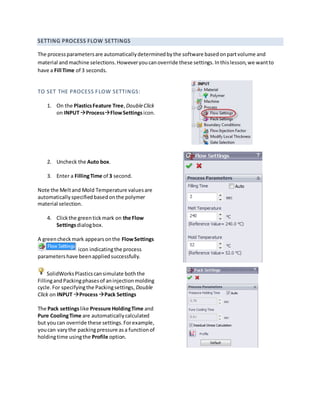
- 7. SETTING PROCESS FLOW SETTINGS The processparametersare automaticallydeterminedbythe software basedonpartvolume and material andmachine selections.Howeveryoucanoverride these settings.Inthislesson,we wantto have a Fill Time of 3 seconds. TO SET THE PROCESS FLOW SETTINGS: 1. On the PlasticsFeature Tree,DoubleClick on INPUTProcessFlowSettingsicon. 2. Uncheck the Auto box. 3. Enter a FillingTime of 3 second. Note the Meltand Mold Temperature valuesare automaticallyspecifiedbasedonthe polymer material selection. 4. Clickthe greentickmark on the Flow Settingsdialogbox. A greencheckmark appearsonthe FlowSettings icon indicatingthe process parametershave beenappliedsuccessfully. SolidWorksPlasticscansimulate boththe FillingandPackingphasesof aninjectionmolding cycle.For specifyingthe Packingsettings, Double Click on INPUT ProcessPack Settings The Pack settingslike Pressure HoldingTime and Pure CoolingTime are automaticallycalculated but youcan override these settings.Forexample, youcan varythe packingpressure asa functionof holdingtime usingthe Profile option.
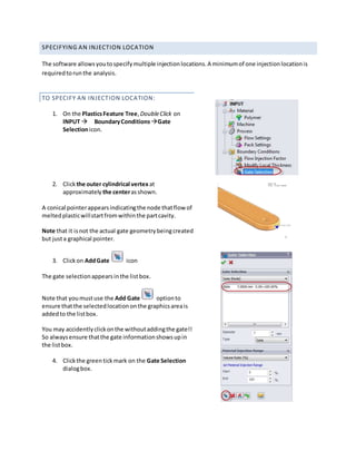
- 8. SPECIFYING AN INJECTION LOCATION The software allowsyoutospecifymultiple injectionlocations.A minimumof one injectionlocationis requiredtorunthe analysis. TO SPECIFY AN INJECTION LOCATION: 1. On the PlasticsFeature Tree,DoubleClick on INPUT BoundaryConditions Gate Selectionicon. 2. Clickthe outer cylindrical vertexat approximately the centerasshown. A conical pointerappearsindicatingthe node thatflow of meltedplasticwillstartfromwithinthe partcavity. Note that it isnot the actual gate geometrybeingcreated but justa graphical pointer. 3. Clickon AddGate icon The gate selectionappearsinthe listbox. Note that youmustuse the Add Gate optionto ensure thatthe selectedlocationonthe graphicsareais addedto the listbox. You may accidentlyclickonthe withoutaddingthe gate!! So alwaysensure thatthe gate informationshowsupin the listbox. 4. Clickthe greentickmark on the Gate Selection dialogbox.
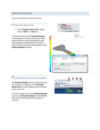
- 9. RUNNING THE ANALYSIS You are nowreadyto run the simulation. TO RUN THE SIMULATION: 1. On the PlasticsFeature Tree,Double Click on RUN Flowicon. The analysisstartsand the AnalysisManager windowappears.Partial resultsonthe model begintoappearas well onthe graphicsarea providinggreatvisual feedback.A logof the solvercalculationdetailsisalsodisplayedinthe AnalysisManager window. MINIMIZING THE ANALYSIS MANAGER The Analysis Manager can be minimizedduring the calculations.Itappearsinthe Windows SystemTray listat the bottomof your windows screenas an icon. To access itagain,clickon the AnalysisManager iconon your WindowsTaskbar. The SolidWorks part can also be closedwhile the analysisis running.
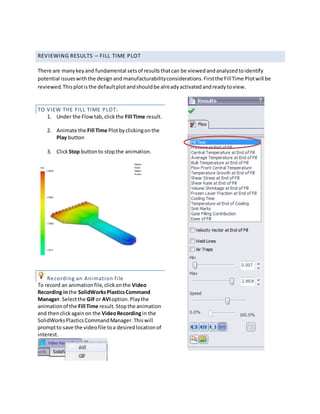
- 10. REVIEWING RESULTS – FILL TIME PLOT There are manykeyand fundamental setsof resultsthatcan be viewedandanalyzedtoidentify potential issueswiththe designand manufacturabilityconsiderations.Firstthe FillTime Plotwill be reviewed.Thisplotisthe defaultplotandshouldbe alreadyactivatedandreadytoview. TO VIEW THE FILL TIME PLOT: 1. Under the Flowtab,clickthe Fill Time result. 2. Animate the Fill Time Plotbyclickingonthe Play button 3. ClickStop buttonto stopthe animation. Recording an Animation file To record an animationfile,clickonthe Video Recording inthe SolidWorksPlasticsCommand Manager. Selectthe GIFor AVIoption.Playthe animationof the Fill Time result.Stopthe animation and thenclickagainon the VideoRecordingin the SolidWorksPlasticsCommandManager.Thiswill promptto save the videofile toa desiredlocationof interest.
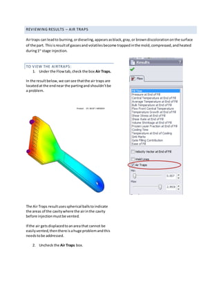
- 11. REVIEWING RESULTS – AIR TRAPS Airtraps can leadto burning,ordieseling,appearsasblack,gray,or browndiscolorationonthe surface of the part. Thisisresultof gassesand volatilesbecome trappedinthe mold,compressed,andheated during1st stage injection. TO VIEW THE AIRTRAPS: 1. Under the Flowtab,check the box Air Traps. In the resultbelow,we cansee thatthe air traps are locatedat the endnear the partingand shouldn’tbe a problem. The Air Traps resultusesspherical ballstoindicate the areas of the cavitywhere the airinthe cavity before injectionmustbe vented. If the air getsdisplacedtoanarea that cannot be easilyvented,thenthere isahuge problemandthis needstobe addressed. 2. Uncheck the Air Traps box.
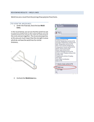
- 12. REVIEWING RESULTS – WELD LINES Weldlinesare a resultfromthe joiningof twopolymerflow fronts. TO VIEW THE WELDLINES: 1. Under the Flowtab,check the box Weld Lines. In the resultbelow,we cansee thatthe weldlinesare locatedaroundthe hole as the material flowsaround the circle and jointogether.The structural properties at thisarea are much lowerthanthe strengthinareas whichdo nothave the weldlinesfor similar thickness. 2. Uncheck the WeldLinesbox.
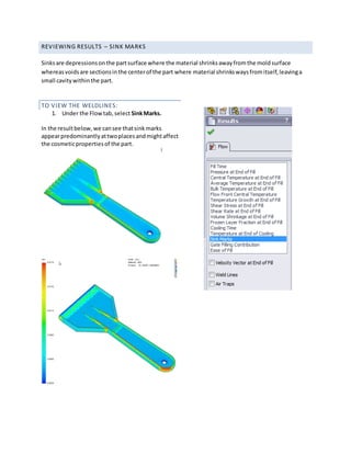
- 13. REVIEWING RESULTS – SINK MARKS Sinksare depressionsonthe partsurface where the material shrinksawayfromthe moldsurface whereasvoidsare sectionsinthe centerof the part where material shrinkswaysfromitself,leavinga small cavitywithinthe part. TO VIEW THE WELDLINES: 1. Under the Flowtab,select SinkMarks. In the resultbelow,we cansee thatsinkmarks appearpredominantlyattwoplacesandmightaffect the cosmeticpropertiesof the part.
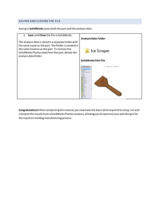
- 14. SAVING AND CLOSING THE FILE SavinginSolidWorkssavesboththe part and the analysisdata. 1. Save and Close the file inSolidWorks. The analysisdatais savedina separate folderwith the same name as the part. The folder iscreatedin the same locationas the part. To remove the SolidWorksPlasticsdatafromthe part,delete the analysisdatafolder. AnalysisData Folder SolidWorksPart File Congratulations! Aftercompletingthistutorial,younow have the basicskillsrequiredtosetup,runand interpretthe resultsfromaSolidWorksPlasticsanalysis,allowingyoutooptimize yourpartdesignsfor the injectionmoldingmanufacturingprocess.

