Lesson03
- 1. LESSON 3 - SOLIDWORKS SIMULATION - OVERVIEW Thisintroductorylessonguidesyouthroughthe stepsrequiredtosetupandsimulatethe testingof the Ice Scraperthroughloads. In thislesson,youwill learnthe following: ï Create a study ï Apply material ï AddFixtures ï Applyload ï Mesh andrun simulation ï Evaluate results
- 2. ADDING IN SOLIDWORKS SIMULATION TO ADD-IN: ClickTools,Add-insand checkthe optionfor SolidWorksSimulation. ClickOK. OPENING THE PART AND ASSIGNING MATERIAL TO OPEN THE PART: Browse to C:MoldToolDie101Lesson03IceScraper_Stress.SLDPRT and Double Clicktoopenthe part inSolidWorks 1. ClickEdit Material (SolidWorks Standardtoolbar). 2. The Material dialogbox appears. 3. In the leftpane,clickthe + plussign nextto SolidWorksMaterials,then clickthe plussignnextto Plastics and selectABS. 4. Mechanical propertiesof ABS appearin the Propertiestab. 5. ClickApplyand Close. 6. The name of the assignedmaterial appearsinthe FeatureManagertree
- 3. CREATING A STUDY 1. Clickthe downarrow on StudyAdvisor (SimulationCommandManager) and selectNewStudy. 2. In the PropertyManager,under Name type Static-1. 3. Under Type,clickStatic 4. ClickOK. The software createsthe studyinthe Simulation studytree.Note the checkmark on the part inthe studytree indicatingthatyouassignedamaterial. .
- 4. APPLY FIXTURE TO MIMIC A HAND GRIP For static analysis,you must apply adequate fixed restraints to stabilizethe model. In this example, you fix the sideof the Ice Scraper. Click the down arrowon Fixtures Advisor (Simulation CommandManager) and select Fixed Geometry, or right-click Fixtures in the study tree and select Fixed Geometry. The Fixture PropertyManager appears. In the graphics area,click thefaces of the sideof the Ice Scraper as showin below. Face<1>, Face<2>, Face<3> and Face<4> appear in the Faces,Edges, Vertices for Fixture box. Click OK. The software fixes the faces to simulatea very hard hand grip and itcreates an ion Fixed-1 in the Simulation study tree.
- 5. APPLYING LOAD ON ICE SCRAPER You apply a 1 lb force normal to the flatface of the Ice Scraper. 1. Click the down arrowon External Loads (Simulation CommandManager) and select Force, or right-click ExternalLoads in the Simulation study tree and select Force. 2. In the PropertyManager, on the Type tab under Type, click Force. 3. In the graphics area,selectthe face as shown for Faces for Force . 4. Under Force Value, select English (IPS) in Unit then type 1 lbf for Force Value . If you change the units after typing a value,the software converts the valueto the new units. 5. Click OK. The software applies 1 lbf forces and creates an icon named Force-1 in the External Loads folder of the Simulation study tree.
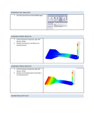
- 6. RUNNING THE ANALYSIS 1. Click Run (Simulation CommandManager). VIEWING STRESS RESULTS 1. In the Simulation study tree, open the Results folder. 2. Double-click Stress1 (-von Mises-) to display theplot. VIEWING STRESS RESULTS 1. In the Simulation study tree, open the Results folder. 2. Double-click Displacement1 (-Disp Res-) to display theplot. ANIMATING ANY PLOT
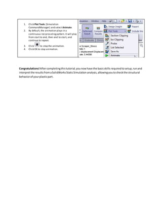
- 7. 1. Click Plot Tools (Simulation CommandManager) and select Animate. 2. By default, the animation plays in a continuous reciprocatingpattern.It will play from start to end, then end to start, and continue to repeat. 3. Click to stop the animation. 4. Click OK to stop animation. Congratulations! Aftercompletingthistutorial,younow have the basicskills requiredtosetup,runand interpretthe resultsfromaSolidWorksStaticSimulation analysis,allowingyouto checkthe structural behaviorof yourplasticpart.


