![Shri Sâad Vidya Mandal Institute of Technology
Topic : LEVER , CLASSIFICATION OF LEVER,TYPES OF
LEVER AND DESIGN PROCIDRE OF BELL CRANK LEVER
GUJARAT TECHNOLOGICAL UNIVERSITY
MACHINE DESIGN AND INDSTRIAL DRAFTING
PREPARED BY :
1] Rana manthan - 170450119044
2] Shah jay - 170450119046
3] Shah rishabh - 170450119047
4] Shah sheril - 170450119048](https://image.slidesharecdn.com/mdidlever-190313112109/85/lever-1-320.jpg)


More Related Content
What's hot (20)
Similar to lever (20)


Recently uploaded (20)


lever
- 1. Shri Sâad Vidya Mandal Institute of Technology Topic : LEVER , CLASSIFICATION OF LEVER,TYPES OF LEVER AND DESIGN PROCIDRE OF BELL CRANK LEVER GUJARAT TECHNOLOGICAL UNIVERSITY MACHINE DESIGN AND INDSTRIAL DRAFTING PREPARED BY : 1] Rana manthan - 170450119044 2] Shah jay - 170450119046 3] Shah rishabh - 170450119047 4] Shah sheril - 170450119048
- 2. CONTENT âĒ Introduction of lever âĒ Classification of lever âĒ Types of lever âĒ Design of levers
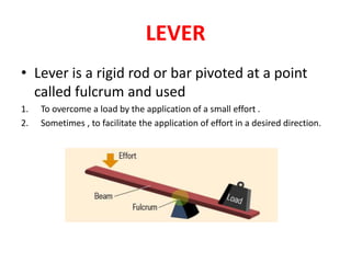
- 3. LEVER âĒ Lever is a rigid rod or bar pivoted at a point called fulcrum and used 1. To overcome a load by the application of a small effort . 2. Sometimes , to facilitate the application of effort in a desired direction.
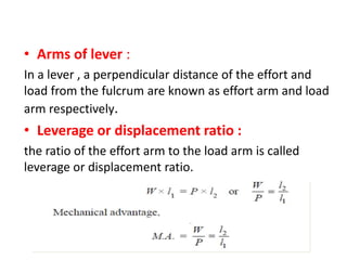
- 4. âĒ Arms of lever : In a lever , a perpendicular distance of the effort and load from the fulcrum are known as effort arm and load arm respectively. âĒ Leverage or displacement ratio : the ratio of the effort arm to the load arm is called leverage or displacement ratio.
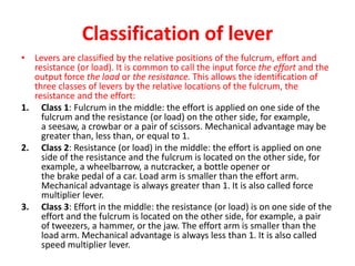
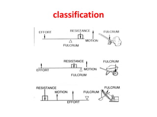
- 5. Classification of lever âĒ Levers are classified by the relative positions of the fulcrum, effort and resistance (or load). It is common to call the input force the effort and the output force the load or the resistance. This allows the identification of three classes of levers by the relative locations of the fulcrum, the resistance and the effort: 1. Class 1: Fulcrum in the middle: the effort is applied on one side of the fulcrum and the resistance (or load) on the other side, for example, a seesaw, a crowbar or a pair of scissors. Mechanical advantage may be greater than, less than, or equal to 1. 2. Class 2: Resistance (or load) in the middle: the effort is applied on one side of the resistance and the fulcrum is located on the other side, for example, a wheelbarrow, a nutcracker, a bottle opener or the brake pedal of a car. Load arm is smaller than the effort arm. Mechanical advantage is always greater than 1. It is also called force multiplier lever. 3. Class 3: Effort in the middle: the resistance (or load) is on one side of the effort and the fulcrum is located on the other side, for example, a pair of tweezers, a hammer, or the jaw. The effort arm is smaller than the load arm. Mechanical advantage is always less than 1. It is also called speed multiplier lever.
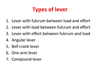
- 7. Types of lever 1. Lever with fulcrum between load and effort 2. Lever with load between fulcrum and effort 3. Lever with effort between fulcrum and load 4. Angular lever 5. Bell crank lever 6. One arm lever 7. Compound lever
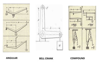
- 8. ANGULAR BELL CRANK COMPOUND
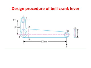
- 9. Design procedure of bell crank lever
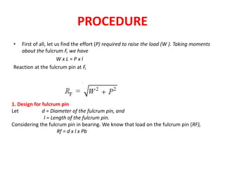
- 10. PROCEDURE âĒ First of all, let us find the effort (P) required to raise the load (W ). Taking moments about the fulcrum F, we have W x L = P x l Reaction at the fulcrum pin at F, 1. Design for fulcrum pin Let d = Diameter of the fulcrum pin, and l = Length of the fulcrum pin. Considering the fulcrum pin in bearing. We know that load on the fulcrum pin (RF), Rf = d x l x Pb
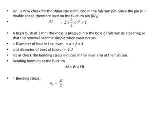
- 11. âĒ Let us now check for the shear stress induced in the fulcrum pin. Since the pin is in double shear, therefore load on the fulcrum pin (RF), âĒ Rf âĒ A brass bush of 3 mm thickness is pressed into the boss of fulcrum as a bearing so that the renewal become simple when wear occurs. âĒ âī Diameter of hole in the lever = d + 2 Ã 3 âĒ and diameter of boss at fulcrum= 2 d âĒ let us check the bending stress induced in the lever arm at the fulcrum. âĒ Bending moment at the fulcrum M = W Ã FB âĒ âī Bending stress,
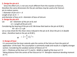
- 12. 2. Design for pin at A Since the effort at A, is not very much different from the reaction at fulcrum, therefore the same dimensions for the pin and boss may be used as for fulcrum pin to reduce spares. âī Diameter of pin at A = d Length of pin at A = l and diameter of boss at A = diameter of boss at fulcrum 3. Design for pin at B Let d1 = Diameter of the pin at B, and L1 = Length of the pin at B. Considering the bearing of the pin at B. We know that load on the pin at B (W ), W = d1 Ã L1 Ã pb Let us now check for the shear stress induced in the pin at B. Since the pin is in double shear , therefore load on the pin at B (W ), W 4. Design of lever It is assumed that the lever extends upto the centre of the fulcrum from the point of application of the load. This assumption is commonly made and results in a slightly stronger section. Considering the weakest section of failure at Y-Y. Let t = Thickness of the lever at Y-Y, and b = Width or depth of the lever at Y-Y. Taking distance from the centre of the fulcrum to Y-Y therefore maximum bending moment at Y-Y,
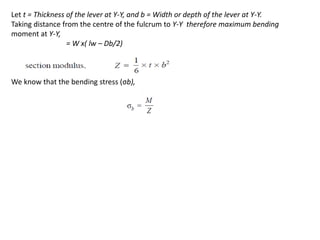
- 13. Let t = Thickness of the lever at Y-Y, and b = Width or depth of the lever at Y-Y. Taking distance from the centre of the fulcrum to Y-Y therefore maximum bending moment at Y-Y, = W x( lw â Db/2) We know that the bending stress (Ïb),
- 14. THANK YOU