Linear-Eigenvalue-Buckling.pdf Mech_BSN_17.0_WS05.1_
- 1. 1 ┬® 2016 ANSYS, Inc. May 31, 2016 Workshop 05.1: Linear (Eigenvalue) Buckling 17.0 Release ANSYS Mechanical Basic Structural Nonlinearities
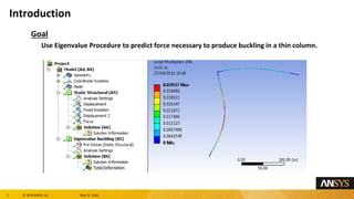
- 2. 2 ┬® 2016 ANSYS, Inc. May 31, 2016 Goal Use Eigenvalue Procedure to predict force necessary to produce buckling in a thin column. Introduction
- 3. 3 ┬® 2016 ANSYS, Inc. May 31, 2016 Model Description ŌĆō L shaped frame represented with 3D Line Bodies ŌĆō Meshed with 3D Beam elements ŌĆō Linear Elastic Material Model Description
- 4. 4 ┬® 2016 ANSYS, Inc. May 31, 2016 Model Description (contŌĆÖd) ŌĆō Horizontal beam fixed at far end. ŌĆō Vertical column simply supported at bottom. ŌĆō All nodes are constrained from movement in Z direction. ŌĆō Compressive unit load (1 lb) applied 10 inches off center of vertical column. Model Description
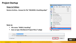
- 5. 5 ┬® 2016 ANSYS, Inc. May 31, 2016 Steps to Follow: Restore ArchiveŌĆ” browse for file ŌĆ£SNLWS05.1-buckling.wbpzŌĆØ Save as ŌĆó File name: ŌĆ£WS05.1-bucklingŌĆØ ŌĆó Save as type: Workbench Project Files (*.wbpj) Project Startup
- 6. 6 ┬® 2016 ANSYS, Inc. May 31, 2016 The project Schematic should look like the picture to the right. ŌĆó From this Schematic, you can see that the Engineering (material) Data and Geometry have already been defined (green check marks). ŌĆó It remains to set up and run the FE model in Mechanical. ŌĆó Open the Engineering Data Cell (highlight and double click OR Right Mouse Button (RMB)>Edit). ŌĆó To see relevant dialog boxes, it might be necessary to go to Utility Menu > View.. ŌĆō Click on ŌĆśPropertiesŌĆÖ and ŌĆśOutlineŌĆÖ. ŌĆó Verify that the units are in US Eng units (lb, in,ŌĆ”) system. If not, fix this by clicking on: ŌĆō Utility Menu > Units > US Engineering(lb, in,ŌĆ”). Project Schematic
- 7. 7 ┬® 2016 ANSYS, Inc. May 31, 2016 Return to Project Schematic From the Analysis Systems Folder of the Toolbox, drag and drop an Eigenvalue Buckling Template onto the Solution Cell of the existing Static Structural Template and Refresh the Project. Open Mechanical (Double click on the ŌĆ£SetupŌĆØ). Project Schematic
- 8. 8 ┬® 2016 ANSYS, Inc. May 31, 2016 The frame model is already set up with the displacement boundary conditions and a unit force load. ŌĆó Highlight the BCs and Load to confirm that the model is properly supported and loaded. Model Description
- 9. 9 ┬® 2016 ANSYS, Inc. May 31, 2016 Note the Static Structural Analysis Settings Specifications: This is a linear analysis ŌĆó Auto Time Stepping = Program Controlled ŌĆó Large Deflection = Off For the Eigenvalue Buckling, we will take the default Analysis Settings to calculate the 1st eigenvalue load required to induce buckling. Analysis Settings
- 10. 10 ┬® 2016 ANSYS, Inc. May 31, 2016 Run the prestressed Eigenvalue buckling solution: Highlight the Solution Branch of the Eigenvalue Buckling Analysis to find the Load Multiplier. Since a unit force load was applied, this load multiplier value (296) represents the magnitude of load necessary to begin a perturbation that leads to buckling. Solve the Model
- 11. 11 ┬® 2016 ANSYS, Inc. May 31, 2016 RMB on the buckling solution to ŌĆ£Create Mode Shape ResultsŌĆØ Postprocessing
- 12. 12 ┬® 2016 ANSYS, Inc. May 31, 2016 Evaluate Total Deformation results (Use results scaling to exaggerate the displacement). Keep this Project open for the next workshop. Postprocessing


