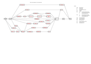
Logic diagram of a typical 132.33k v power substaion
•
0 likes•241 views

This document provides a typical logic diagram of the process for a 132/33kV substation project. The diagram shows the key stages are site preparation, civil works like power transformer foundation and cable installation, equipment delivery and installation, commissioning, and training. It also outlines the design, approval, and review stages including base design submittal, detailed design submittal, and design approval that must occur before construction and installation can begin.

Logic diagram of a typical 132.33k v power substaion
- 1. TYPICAL LOGIC DIAGRAM OF 132/33kV SUBSTATION LEGEND: KOM Kick Off Meeting PO Purchase Order SP Site Preparation ST Usually Operational Sparepart CW Civil Work TR Training BDS EL Base Design Submittal Electrical Em Base Design Submittal Mechanical C Base Design Submittal Civil BDA EL Base Design Approval Electrical Em Base Design Approval Mechanical C Base Design Approval Civil DDS Detail Design Submittal DDA Detail Design Approval IFC Issued For Construction BDR Base Design Review TCC Technical Completion Certificate PCC Preliminary Comp Cert FAC Final Acceptance Cert DF Basement CWComplete SP Preparation KOM P.O. TR-Factory TCC PAC FAC Manufacture Transport Installation Commissionin SP Handover Install Cable Mobilization CW Power Trans Reinf. Conc, RW&T DDS (E,C,Em) BDS(EL) Dummy BDS(Em) Equip L.O. BDS(C) BDSApp DDAp(E,C,Em) IFC ST BDSComp BDRMeeting TR (SiTe)
- 2. Mechanical