Logic synthesis with synopsys design compiler
- 1. Logic Synthesis with SYNOPSYS DESIGN COMPILER Presenters: Muhammad Umer Kakli Muhammad Naeem Tayyab
- 2. Agenda ’é¦ASIC Design Flow ’é¦Logic Synthesis ’é¦Logic Synthesis Process ’é¦Design Compiler ’é¦DC Flow ’é¦ Synthesis Steps ’é¦Getting Started with DC ’é¦Q & A
- 3. ASIC Design Flow Dr. Osman HasanŌĆÖs Lectures on ASIC Design Methodology, SEECS, NUST, 2011
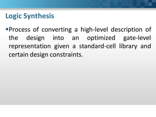
- 4. Logic Synthesis ’é¦Process of converting a high-level description of the design into an optimized gate-level representation given a standard-cell library and certain design constraints.
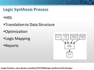
- 5. Logic Synthesis Process ’é¦HDL ’é¦Translation to Data Structure ’é¦Optimization ’é¦Logic Mapping ’é¦Reports Image Courtesy: www.docstoc.com/docs/27375300/Logic-Synthesis-with-Synopsys
- 6. Logic Synthesis Tools ’é¦ŌĆ£Design CompilerŌĆØ by Synopsys ’é¦ŌĆ£Encounter RTL CompilerŌĆØ by Cadence ’é¦ŌĆ£TalusDesignŌĆØ by Magma Design Automation
- 7. The Design Compiler ’é¦It is the core of the Synopsys synthesis software products. It includes tools that synthesis the HDL designs into optimized technology-dependent, gate level designs. It can optimize for speed, area and power. ’é¦Interfaces - Design Vision - dc_shell
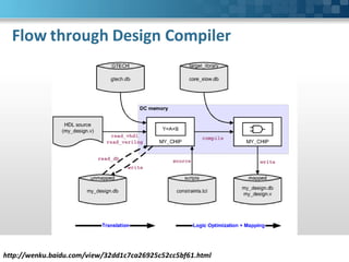
- 8. Flow through Design Compiler http://wenku./view/32dd1c7ca26925c52cc5bf61.html
- 9. Logic Synthesis Steps ’é¦Develop HDL Files ’é¦Specify Libraries ’é¦Read Design ’é¦Define Design Environment ’é¦Set Design Constraint ’é¦Optimize the Design ’é¦Analyze and Resolve the Design Problems
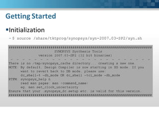
- 10. Getting Started ’é¦Initialization - $ source /share/tktprog/synopsys/syn-2007.03-SP2/syn.sh
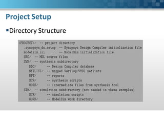
- 12. Project Setup (Contd.) ’é¦Setup File - .synposys_dc.setup
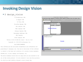
- 13. Invoking Design Vision ’é¦ $ design_vision
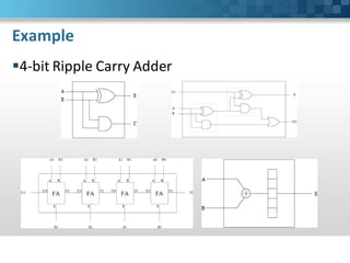
- 14. Example ’é¦4-bit Ripple Carry Adder
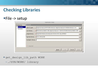
- 15. Checking Libraries ’é¦File -> setup ’é¦ get_design_lib_path WORK - ./SYN/WORK/ library
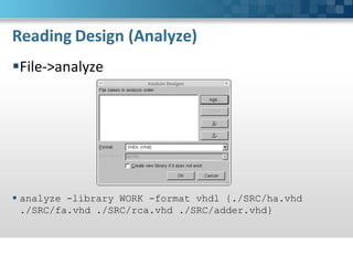
- 16. Reading Design ’é¦Load design into Design Compiler Memory. It consists of two operations - Analyzing design: Top level of Hierarchy - Elaborating design: Lower level block associated
- 17. Reading Design (Analyze) ’é¦File->analyze ’é¦ analyze -library WORK -format vhdl {./SRC/ha.vhd ./SRC/fa.vhd ./SRC/rca.vhd ./SRC/adder.vhd}
- 18. Reading Design (Elaborate) ’é¦File->elaborate ’é¦ elaborate ADDER -architecture RTL -library WORK - parameters"N=4"
- 19. Checking Design Structure ’é¦Using Hierarchy Browser
- 20. Checking Design Structure (Contd.) ’é¦Creating Design Schematic
- 21. Look for Multiple Designs ’é¦ check_design -multiple_designs
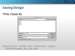
- 22. Saving Design ’é¦File->Save As ’é¦ write_file -format ddc -hierarchy -output ./SYN/DDC/adder_N4_elab.ddc
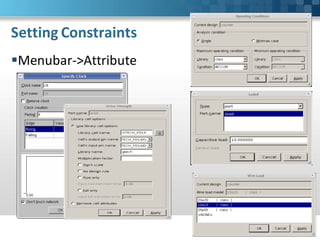
- 23. Setting Constraints ’é¦Create or modify a clock ’é¦Set input and output delays ’é¦ Set drive strengths ’é¦ Set loads ’é¦Select operating conditions ’é¦ Choose a wire load model
- 25. Setting Constraints (Contd.) ’é¦ create_clock -name "clk" -period 4 -waveform {0 2} {clk} set_clock_uncertainty 0.1 clk set_clock_latency 0.2 clk set_clock_transition 0.1 clk set_dont_touch_network clk ’é¦ set_driving_cell -library umcl18g212t3_tc_180V_25C -lib_cell HDDFFPB1 -pin Q [get_ports a] set_driving_cell -library umcl18g212t3_tc_180V_25C -lib_cell HDINVD1 -pin Z [get_ports b] set_load [load_of umcl18g212t3_tc_180V_25C/HDDFFPB1/D] [get_ports s] ’é¦ set_input_delay 0.67 [get_ports b] -clock clk set_output_delay 0.5 [get_ports s] -clock clk ’é¦ set_max_area 1000
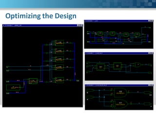
- 26. Optimizing the Design ’é¦Design->Compile ’é¦ compile
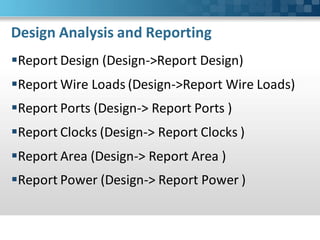
- 28. Design Analysis and Reporting ’é¦Report Design (Design->Report Design) ’é¦Report Wire Loads (Design->Report Wire Loads) ’é¦Report Ports (Design-> Report Ports ) ’é¦Report Clocks (Design-> Report Clocks ) ’é¦Report Area (Design-> Report Area ) ’é¦Report Power (Design-> Report Power )
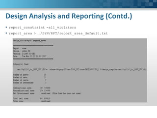
- 29. Design Analysis and Reporting (Contd.) ’é¦ report_constraint -all_violators ’é¦ report_area > ./SYN/RPT/report_area_default.txt
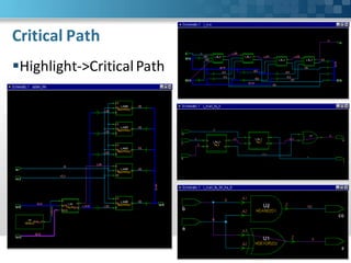
- 31. Critical Path (Full Path at Glance) ’é¦Schematic -> New Path Schematic View
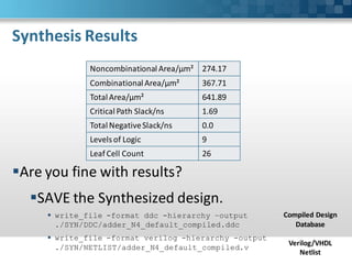
- 32. Synthesis Results Noncombinational Area/┬Ąm┬▓ 274.17 Combinational Area/┬Ąm┬▓ 367.71 Total Area/┬Ąm┬▓ 641.89 Critical Path Slack/ns 1.69 Total Negative Slack/ns 0.0 Levels of Logic 9 Leaf Cell Count 26 ’é¦Are you fine with results? ’é¦SAVE the Synthesized design. ’é¦ write_file -format ddc -hierarchy ŌĆōoutput Compiled Design ./SYN/DDC/adder_N4_default_compiled.ddc Database ’é¦ write_file -format verilog -hierarchy -output Verilog/VHDL ./SYN/NETLIST/adder_N4_default_compiled.v Netlist
- 33. References ’é¦ http://www.tkt.cs.tut.fi/tools/public/tutorials/synopsys/design_co mpiler/gsdc.html#read_design ’é¦ http://www.engr.sjsu.edu/tle/271_DV_tut.pdf ’é¦ http://www.ece.wisc.edu/~morrow/ECE551/tutorials/DesignVision Tutorial_f07.pdf
- 34. Q&A









![Setting Constraints (Contd.)
’é¦ create_clock -name "clk" -period 4 -waveform {0 2} {clk}
set_clock_uncertainty 0.1 clk
set_clock_latency 0.2 clk
set_clock_transition 0.1 clk
set_dont_touch_network clk
’é¦ set_driving_cell -library umcl18g212t3_tc_180V_25C -lib_cell
HDDFFPB1 -pin Q [get_ports a]
set_driving_cell -library umcl18g212t3_tc_180V_25C -lib_cell HDINVD1
-pin Z [get_ports b] set_load [load_of
umcl18g212t3_tc_180V_25C/HDDFFPB1/D] [get_ports s]
’é¦ set_input_delay 0.67 [get_ports b] -clock clk
set_output_delay 0.5 [get_ports s] -clock clk
’é¦ set_max_area 1000](https://image.slidesharecdn.com/logicsynthesiswithsynopsysdesigncompiler-120619134032-phpapp02/85/Logic-synthesis-with-synopsys-design-compiler-25-320.jpg)

