

![WORKPIECE
TOOL
t1
╬▒
Shear
plane
Friction
plane
Vertical
plane
Vs
Vc
Vf
Žå
╬▒
Žå
AC
B
t1
sinąż = t1 / AB
90-ąż
sin(90- ąż+ ╬▒ ) = sin (90-(ąż-╬▒)) = cos(ąż-╬▒) = t2/AB
t1 = AB*sinąż
t2 = AB cos (ąż-╬▒)
Therefore
t1/t2 = (AB*sinąż) / (AB*cos(ąż-╬▒) )
r = sinąż / cos (ąż-╬▒)
r = sinąż / ( cosąż*cos╬▒+ sinąż*sin╬▒ )
r = ( sinąż /cos ąż ) / [( cosąż*cos╬▒+ sinąż*sin╬▒ ) / cosąż]
r = tanąż/ (cos╬▒ + tanąż*sin╬▒ )
rcos╬▒ + r*tanąż*sin╬▒ = tanąż
tanąż -r*tanąż*sin╬▒ = rcos╬▒
tanąż (1- rsin╬▒) = rcos ╬▒
tanąż = rcos╬▒ / (1- rsin╬▒)
From triangle ABC & ACD
D
90-ąż+╬▒
ąż-╬▒
RELATION BETWEEN R, ╬” AND ╬▒](https://image.slidesharecdn.com/mechanics-180924133955-180925065357/85/Mechanics-of-Orthogonal-Cutting-3-320.jpg)
![WORKPIECE
TOOL
t1
╬▒
Shear
plane
Friction
plane
Vertical
plane
Vs
Vc
Vf
Žå
Vc
Vf Vs
Žå90-╬▒
90-(ąż-╬▒)
By applying SINE rule
(Vf / sinąż) =[Vs / sin(90-╬▒)] = [Vc/sin(90-(ąż-╬▒)]
(Vf / sinąż) = (Vs / cos╬▒) = [Vc/cos(ąż-╬▒)]
Vf = [Vc*sin ╬▒ /cos(ąż-╬▒)]
Vf = Vc*r
Vs = [(Vc*cos ╬▒ /cos(ąż-╬▒)]
VELOCITY RELATIONSHIPS](https://image.slidesharecdn.com/mechanics-180924133955-180925065357/85/Mechanics-of-Orthogonal-Cutting-4-320.jpg)


![Shear area = As = W*t1 / sin ╬”
Shear stress = Žä = Fs / As Žä = Fs sin╬” / (w*t1)
Shear strain = Ų│ = Cot ╬” + tan (╬”-╬▒) = cos / [sin ╬”*cos (╬”-╬▒)]
Shear strain rate = Vs/ts
WORKPIECE
t1
Fs
Žå W
Vs
The minimum value of shear strain when rake angle is zero
Shear strain = Ų│ = Cot ╬” + tan ╬”
(d/d╬”) {cot ╬” + tan ╬” } = 0
-cosec^2 ╬” + sec^2 ╬” =0
-(1/sin^2 ╬”)+ (1/cos^2 ╬”) =0
cos^2 ╬”-sin^2 ╬”=0
[(1-cos 2╬”)/2] - [(1-sin 2╬”)/2] =0
2cos 2 ╬” = 0
2╬” =90
╬” =45
For minimum value
2╬” - ╬▒ =90
For orthogonal cutting
Depth of cut = t1 = feed*╬Ė ( ╬Ė is side cutting edge angle )
Width of cut = t1/ sin ╬Ė](https://image.slidesharecdn.com/mechanics-180924133955-180925065357/85/Mechanics-of-Orthogonal-Cutting-8-320.jpg)
![Fc
Ft
N
F
┬Ą = Tan╬▓ = F/N = Ft/Fc
But when Ft > Fc, ╬▓ > 45 ┬Ą > 1
In this case use formulae for finding ┬Ą
The classical friction theory
┬Ą = [ln ( 1/r)] / [( ŽĆ/2) ŌĆō ╬▒]
Actuvally the value of ┬Ą is always comes less than one
Ft < Fc, ╬▓ < 45 ┬Ą < 1](https://image.slidesharecdn.com/mechanics-180924133955-180925065357/85/Mechanics-of-Orthogonal-Cutting-9-320.jpg)


More Related Content
What's hot (20)
Similar to Mechanics of Orthogonal Cutting (20)


![MTORSION [EngineeringDuniya.co MTORSION [EngineeringDuniya.com].pptm].ppt](https://cdn.slidesharecdn.com/ss_thumbnails/mtorsionengineeringduniya-241112074730-b7e902c3-thumbnail.jpg?width=560&fit=bounds)


Recently uploaded (20)


Mechanics of Orthogonal Cutting
- 2. t1 is un-cut chip thickness t2 is cut chip thickness r is chip thickness ratio r = t1/t2 < 1 ( t1 < t2) k = 1/r = chip reduction coefficient ╬▒ is rake angle Žå is shear angle Assumptions 1. No contact at the flank. 2. Width of chip remains constant. 3. Uniform cutting velocity. 4. A continues chip is produced. 5. Volumetric changes of material during machining is zero. That is Volume before cutting = volume after cutting t1 *b*l1 = t2*b*l2 t1/t2 = l2/l1 = r Also we can say that volumetric flow rate is also equal t1*b*Vc = t2*b*Vf t1/t2 = Vf/ Vc Vc is cutting velocity Vf is chip flow velocity Vs is shear velocity WORKPIECE t1 ╬▒ Shear plane Friction planeVertical plane Vs Vc Vf TOOL width Žå
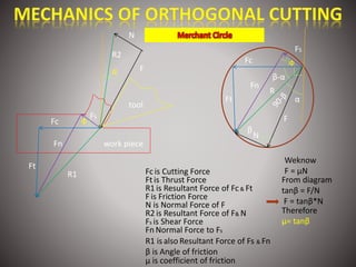
- 3. WORKPIECE TOOL t1 ╬▒ Shear plane Friction plane Vertical plane Vs Vc Vf Žå ╬▒ Žå AC B t1 sinąż = t1 / AB 90-ąż sin(90- ąż+ ╬▒ ) = sin (90-(ąż-╬▒)) = cos(ąż-╬▒) = t2/AB t1 = AB*sinąż t2 = AB cos (ąż-╬▒) Therefore t1/t2 = (AB*sinąż) / (AB*cos(ąż-╬▒) ) r = sinąż / cos (ąż-╬▒) r = sinąż / ( cosąż*cos╬▒+ sinąż*sin╬▒ ) r = ( sinąż /cos ąż ) / [( cosąż*cos╬▒+ sinąż*sin╬▒ ) / cosąż] r = tanąż/ (cos╬▒ + tanąż*sin╬▒ ) rcos╬▒ + r*tanąż*sin╬▒ = tanąż tanąż -r*tanąż*sin╬▒ = rcos╬▒ tanąż (1- rsin╬▒) = rcos ╬▒ tanąż = rcos╬▒ / (1- rsin╬▒) From triangle ABC & ACD D 90-ąż+╬▒ ąż-╬▒ RELATION BETWEEN R, ╬” AND ╬▒
- 4. WORKPIECE TOOL t1 ╬▒ Shear plane Friction plane Vertical plane Vs Vc Vf Žå Vc Vf Vs Žå90-╬▒ 90-(ąż-╬▒) By applying SINE rule (Vf / sinąż) =[Vs / sin(90-╬▒)] = [Vc/sin(90-(ąż-╬▒)] (Vf / sinąż) = (Vs / cos╬▒) = [Vc/cos(ąż-╬▒)] Vf = [Vc*sin ╬▒ /cos(ąż-╬▒)] Vf = Vc*r Vs = [(Vc*cos ╬▒ /cos(ąż-╬▒)] VELOCITY RELATIONSHIPS
- 5. work piece tool R2 F N Fc Ft R1 FS Fn Žå ╬▒ FS R F N ╬▓ Žå Ft Fc Fn ╬▒ ╬▓-╬▒ Fc is Cutting Force Ft is Thrust Force R1 is Resultant Force of Fc & Ft F is Friction Force N is Normal Force of F R2 is Resultant Force of F& N Fs is Shear Force Fn Normal Force to Fs R1 isalso Resultant Force of Fs & Fn Weknow F = ┬ĄN From diagram tan╬▓ = F/N F = tan╬▓*N Therefore ┬Ą= tan╬▓ ╬▓ is Angle of friction ┬Ą is coefficient of friction
- 6. Ft Fc ╬▓-╬▒ R FS R F N ╬▓ Žå Ft Fc Fn ╬▒ ╬▓ -╬▒ R = (Fc ^2) + (Fv^2) Tan(╬▓-╬▒) = Fc /Ft R Žå Fn R = (Fs^2) + (Ns^2) FS Tan(╬▓-╬▒+Žå) = Fs/Ns ╬▓ ╬▓-╬▒ ╬▒ R = (F^2) + (N^2) R F N Theories of Angles Lee & Shaffer theory : ╬”+╬▓-╬▒ = 45 Stabler theory : ╬”+╬▓-(╬▒/2)= 45 Merchant Constant (Cm) : 2╬”+╬▓-╬▒ Energy for Cutting (Ec) = Fc * VC Energy for friction (Ef) = F * VF Energy for shearing (Es) = Fs * Vs Percentage of energy loss in friction = (Ec/Ef)*100 Percentage of energy loss in shearing = (Ec/Ef)*100
- 7. R F N ╬▓ Žå Ft Fc ╬▒ ╬▓ -╬▒ A O D C E G B ╬▒ 9O-╬▒ 9O-╬▒ Relationship of Fs & Fn with Fc & Ft Fn = AE = AD+DE = DE+CB = Fc sin Žå + Ft cos Žå Fs = OA = OB-AB = OB-BC = Fc cos Žå - Ft sin Žå Relationship of F & N with Fc & Ft F= OA = CB = CG+GB = ED+GB = Fc sin ╬▒ + Ft cos ╬▒ N= AB = OD ŌĆōCD = OD- GE = Fc COS ╬▒ - Ft sin╬▒ FS R ╬” Ft Fc Fn ╬▒ ╬▓ -╬▒ O B A C G E 9O-╬” 9O-╬”
- 8. Shear area = As = W*t1 / sin ╬” Shear stress = Žä = Fs / As Žä = Fs sin╬” / (w*t1) Shear strain = Ų│ = Cot ╬” + tan (╬”-╬▒) = cos / [sin ╬”*cos (╬”-╬▒)] Shear strain rate = Vs/ts WORKPIECE t1 Fs Žå W Vs The minimum value of shear strain when rake angle is zero Shear strain = Ų│ = Cot ╬” + tan ╬” (d/d╬”) {cot ╬” + tan ╬” } = 0 -cosec^2 ╬” + sec^2 ╬” =0 -(1/sin^2 ╬”)+ (1/cos^2 ╬”) =0 cos^2 ╬”-sin^2 ╬”=0 [(1-cos 2╬”)/2] - [(1-sin 2╬”)/2] =0 2cos 2 ╬” = 0 2╬” =90 ╬” =45 For minimum value 2╬” - ╬▒ =90 For orthogonal cutting Depth of cut = t1 = feed*╬Ė ( ╬Ė is side cutting edge angle ) Width of cut = t1/ sin ╬Ė
- 9. Fc Ft N F ┬Ą = Tan╬▓ = F/N = Ft/Fc But when Ft > Fc, ╬▓ > 45 ┬Ą > 1 In this case use formulae for finding ┬Ą The classical friction theory ┬Ą = [ln ( 1/r)] / [( ŽĆ/2) ŌĆō ╬▒] Actuvally the value of ┬Ą is always comes less than one Ft < Fc, ╬▓ < 45 ┬Ą < 1
- 10. ŌĆó Taylorstool life equation:- ŌĆóVTn=C ŌĆó Tool life equation (generalized)ŌĆō ŌĆóVTnfn1dn2=C ŌĆó Tool life exponents n,n1, n2 are found by plotting experimental data on log V ŌĆō log T,log TŌĆō log fand log TŌĆō log d scales.
- 11. Determination of toollife constants n,n1, n2 ŌĆó Longand expensive test, involves considerableamount of material, labor and machiningtime. ŌĆó Recourseis taken to experimental design techniques suchasfactorial design, multiple regression analysis and response surface methodology to reduce cost and no. of observations.