際際滷

際際滷Share a Scribd company logo
INTRODUCTION TO MICROWAVE
ENGINEERING: Characteristics &
Applications
CT 4th Semester 2018
By- Parismita A. Kashyap
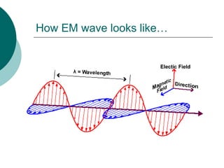
How EM wave looks like
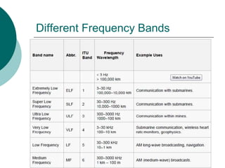
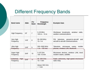
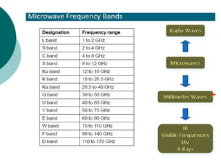
Different Frequency Bands
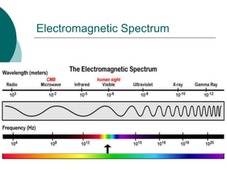
Electromagnetic Spectrum
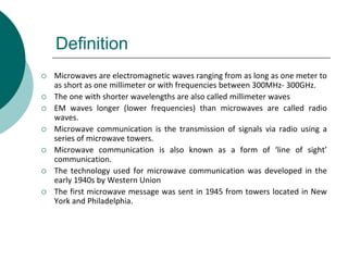
Definition
 Microwaves are electromagnetic waves ranging from as long as one meter to
as short as one millimeter or with frequencies between 300MHz- 300GHz.
 The one with shorter wavelengths are also called millimeter waves
 EM waves longer (lower frequencies) than microwaves are called radio
waves.
 Microwave communication is the transmission of signals via radio using a
series of microwave towers.
 Microwave communication is also known as a form of line of sight
communication.
 The technology used for microwave communication was developed in the
early 1940s by Western Union
 The first microwave message was sent in 1945 from towers located in New
York and Philadelphia.
Microwave 1st class
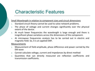
Characteristic Features
Small Wavelength in relation to component sizes and circuit dimensions
1. Standard circuit theory cannot be used to solve network problems.
2. The phase of voltage and current changes significantly over the physical
extent of the device.
3. At much lower frequencies the wavelength is large enough and there is
insignificant phase variations across the dimensions of the component.
4. At microwave frequencies analysis has to be carried out in electric and
magnetic field. So, it is an applied EMF.
Measurements
1. Measurement of field amplitude, phase difference and power carried by the
EM wave
2. Cannot calculate voltage, current and impedances by direct method
3. Quantities that can directly measured are reflection coefficients and
transmission coefficients.
Characteristic Features
Different appearance of microwave circuit components
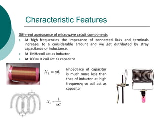
1. At high frequencies the impedance of connected links and terminals
increases to a considerable amount and we get distributed by stray
capacitance or inductance.
2. At 1MHz coil act as inductor
3. At 100MHz coil act as capacitor
LXL 件
C
XC

1

Impedance of capacitor
is much more less than
that of inductor at high
frequency; so coil act as
capacitor
Applications
Applications
Communication (Wireless: Terrestrial systems)
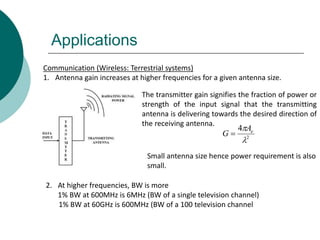
1. Antenna gain increases at higher frequencies for a given antenna size.
The transmitter gain signifies the fraction of power or
strength of the input signal that the transmitting
antenna is delivering towards the desired direction of
the receiving antenna.
2
4

 eA
G 
2. At higher frequencies, BW is more
1% BW at 600MHz is 6MHz (BW of a single television channel)
1% BW at 60GHz is 600MHz (BW of a 100 television channel
Small antenna size hence power requirement is also
small.
Applications
3. They can penetrate through fog, dust, foliage and even buildings and
vehicles to some extent.
4. Since 1950s microwave radio systems has become popular for long distance
telephone communication
5. Because of the curvature of the earth repeaters are placed at about 150km
apart.
6. These systems provide needed transmission BW and reliability.
Satellite
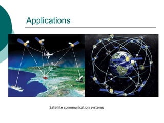
1. Satellites in a geosynchronous earth orbit are positioned approx 36000km
above the earth and remain in a fixed position relative to the surface.
2. Frequency bands used are C, X, Ku, Ka
3. Inside sea, OFC has replaced satellites for transoceanic connections as they
are economical avoids annoying delay.
Applications
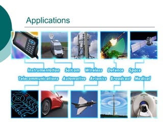
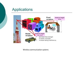
Wireless communication systems
Applications
Satellite communication systems
Applications
Radio Detection and Ranging (RADAR)
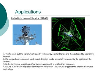
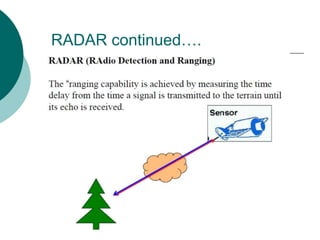
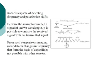
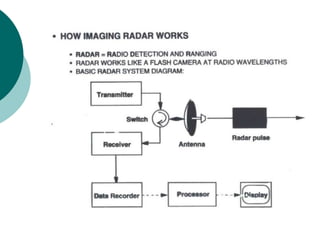
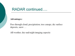
1. The Tx sends out the signal which is partly reflected by a distant target and then detected by a sensitive
receiver.
2. If a narrow beam antenna is used, target direction can be accurately measured by the position of the
antenna.
3. Reflection from a target is significant when wavelength is smaller than frequency.
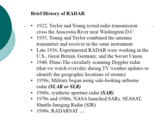
4. RADAR is practically applicable at microwave frequency. Thus, RADAR triggered the birth of microwave
technology.
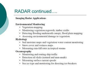
RADAR continued.
RADAR continued.
RADAR continued.
RADAR continued.
RADAR continued.
RADAR continued.
Applications
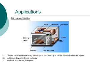
Microwave Heating
1. Domestic microwave heating: Heat is produced directly at the locations of dielectric losses.
2. Industrial: Drying in textile industry
3. Medical: Microwave diathermy.
Applications
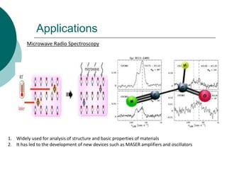
Microwave Radio Spectroscopy
1. Widely used for analysis of structure and basic properties of materials
2. It has led to the development of new devices such as MASER amplifiers and oscillators

More Related Content

Microwave 1st class

  • 1. INTRODUCTION TO MICROWAVE ENGINEERING: Characteristics & Applications CT 4th Semester 2018 By- Parismita A. Kashyap
  • 2. How EM wave looks like
  • 6. Definition Microwaves are electromagnetic waves ranging from as long as one meter to as short as one millimeter or with frequencies between 300MHz- 300GHz. The one with shorter wavelengths are also called millimeter waves EM waves longer (lower frequencies) than microwaves are called radio waves. Microwave communication is the transmission of signals via radio using a series of microwave towers. Microwave communication is also known as a form of line of sight communication. The technology used for microwave communication was developed in the early 1940s by Western Union The first microwave message was sent in 1945 from towers located in New York and Philadelphia.
  • 8. Characteristic Features Small Wavelength in relation to component sizes and circuit dimensions 1. Standard circuit theory cannot be used to solve network problems. 2. The phase of voltage and current changes significantly over the physical extent of the device. 3. At much lower frequencies the wavelength is large enough and there is insignificant phase variations across the dimensions of the component. 4. At microwave frequencies analysis has to be carried out in electric and magnetic field. So, it is an applied EMF. Measurements 1. Measurement of field amplitude, phase difference and power carried by the EM wave 2. Cannot calculate voltage, current and impedances by direct method 3. Quantities that can directly measured are reflection coefficients and transmission coefficients.
  • 9. Characteristic Features Different appearance of microwave circuit components 1. At high frequencies the impedance of connected links and terminals increases to a considerable amount and we get distributed by stray capacitance or inductance. 2. At 1MHz coil act as inductor 3. At 100MHz coil act as capacitor LXL 件 C XC 1 Impedance of capacitor is much more less than that of inductor at high frequency; so coil act as capacitor
  • 11. Applications Communication (Wireless: Terrestrial systems) 1. Antenna gain increases at higher frequencies for a given antenna size. The transmitter gain signifies the fraction of power or strength of the input signal that the transmitting antenna is delivering towards the desired direction of the receiving antenna. 2 4 eA G 2. At higher frequencies, BW is more 1% BW at 600MHz is 6MHz (BW of a single television channel) 1% BW at 60GHz is 600MHz (BW of a 100 television channel Small antenna size hence power requirement is also small.
  • 12. Applications 3. They can penetrate through fog, dust, foliage and even buildings and vehicles to some extent. 4. Since 1950s microwave radio systems has become popular for long distance telephone communication 5. Because of the curvature of the earth repeaters are placed at about 150km apart. 6. These systems provide needed transmission BW and reliability. Satellite 1. Satellites in a geosynchronous earth orbit are positioned approx 36000km above the earth and remain in a fixed position relative to the surface. 2. Frequency bands used are C, X, Ku, Ka 3. Inside sea, OFC has replaced satellites for transoceanic connections as they are economical avoids annoying delay.
  • 15. Applications Radio Detection and Ranging (RADAR) 1. The Tx sends out the signal which is partly reflected by a distant target and then detected by a sensitive receiver. 2. If a narrow beam antenna is used, target direction can be accurately measured by the position of the antenna. 3. Reflection from a target is significant when wavelength is smaller than frequency. 4. RADAR is practically applicable at microwave frequency. Thus, RADAR triggered the birth of microwave technology.
  • 22. Applications Microwave Heating 1. Domestic microwave heating: Heat is produced directly at the locations of dielectric losses. 2. Industrial: Drying in textile industry 3. Medical: Microwave diathermy.
  • 23. Applications Microwave Radio Spectroscopy 1. Widely used for analysis of structure and basic properties of materials 2. It has led to the development of new devices such as MASER amplifiers and oscillators