Mixed Signal VLSI Design
- 1. A PROJECT REPORT ON ŌĆ£4-BIT BARREL SHIFTERŌĆØ Nikhil Umesh Dantkale Class-TE Div-N Roll No.-23 DEPARTMENT OF ELECTRONICS ENGINEERING VISHWAKARMA INSTITUTE OF TECHNOLOGY (An Autonomous Institute, Affiliated to Pune University) Academic Year 2012-13
- 2. CERTIFICATE VISHWAKARMA INSTITUTE OF TECHNOLOGY Department of Electronics Engineering This is to certify that Nikhil Umesh Dantkale (Roll No:N-23) has submitted a project on the topic ŌĆ£ 4-BIT BARREL SHIFTER ŌĆØin Mixed Signal VLSI Design LAB (VLSI Honor) for the academic year 2012-13. Prof. A.V. Pedgaonkar Prof. A.M.Chopde Assistant Professor Head of the Department Electronics Engineering
- 3. ACKNOWLEDGEMENT It is matter of great pleasure for me to submit this project report on ŌĆ£4-BIT BARREL SHIFTERŌĆØ, as a part of curriculum for award of ŌĆ£Bachelor of Engineering in Electronics & TelecommunicationŌĆØ. I am thankful to my project guide Prof. A. V. PEDGAONKAR Assistant Professor in Electronics Engineering Department for her constant encouragement and able guidance. I am also thankful to Prof. A. M. Chopde, Head of Electronics Engineering Department for his valuable support. I take this opportunity to express my deep sense of gratitude towards those, who have helped me in various ways, for preparing my project. At the last but not least, I am thankful to my parent, who had encouraged & inspired me with their blessings. (Name of Student) Nikhil U. Dantkale
- 4. TABLE OF CONTENT Sr No. Content Page No 1. Introduction 6 2. Implementation of Barrel Shifter using 2:1 Multiplexer 7 3. Transistor Level Diagram of 2:1 Multiplexer 8 4. Code For 4-Bit Barrel Shifter using 2:1 Multiplexer 9 5. OUTPUT WAVEFORMS OF BARREL SHIFTER 11 6. Advantages of Barrel shifter 12 7. APPLICATIONS OF BARREL SHIFTER 13
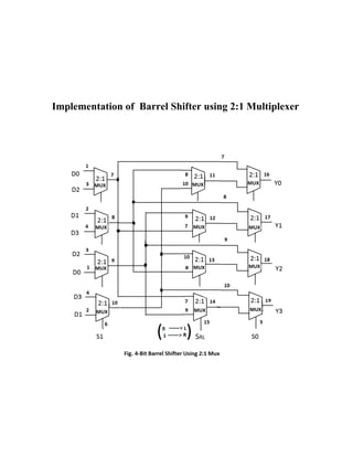
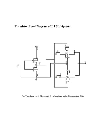
- 5. ABSTRACT A barrel shifter is a combinational logic circuit with n data inputs, n data outputs, and a set of control inputs that specify how to shift the data between input and output. In this project we have implemented 4-Bit Barrel Shifter which has 4 data inputs D0,D1,D2,D3 and 4 data outputs Y0,Y1,Y2,Y3 using VLSI Technology. Three modules have been designed which consist of four 2:1 Multiplexer in each module. Each module has one select line. Select lines of first and third module determines how many bits to shift. Select line of second module specifies shifting of data either to left or right. Third module provides you your desired output. We have implemented 2:1 mux using transmission gates which requires 6 transistors. Thus we have implemented 4-Bit Barrel Shifter using 72 transistors. We designed a 4 bit Barrel Shifter that shifts data from an input to an output depending on the combination of two select lines. Our design of the Barrel shifter allows for an increase in the number of input bits without having to modify the existing design.
- 6. INTRODUCTION A barrel shifter is a digital circuit that can shift a data word by a specified number of bits. It can be implemented as a sequence of multiplexers (mux.), and in such an implementation the output of one mux is connected to the input of the next mux in a way that depends on the shift distance. A barrel shifter that is part of a microprocessor CPU can typically specify the direction of shift (left or right), the type of shift (circular, arithmetic, or logical), and the amount of shift (typically 0 to n-1 bits, but sometimes 1 to n bits), where 'n' is data inputs and data outputs of barrel shifter. Barrel shifters are often required for performing data shifting and rotation in many key computer operations from address decoding to computer arithmetic. Barrel shifter circuits are essential elements in the design of data paths for DSP applications. A significant reduction in area and power required by the barrel shifter circuit is achieved by implementing rightward operations as operations in leftward direction. A significant reduction in delay is possible by reducing the length of critical path.
- 7. Implementation of Barrel Shifter using 2:1 Multiplexer
- 8. Transistor Level Diagram of 2:1 Multiplexer Fig. Transistor Level Diagram of 2:1 Multiplexer using Transmission Gate
- 9. Code For 4-Bit Barrel Shifter using 2:1 Multiplexer *barrel shifter .subckt two 1 4 5 6 .model p pmos .model n nmos m1 3 1 0 0 n m2 3 1 2 2 p m3 4 3 6 0 n m4 6 1 4 2 p m5 5 1 6 0 n m6 6 3 5 2 p vdd 2 0 dc 5v .ends X1 6 1 3 7 two X2 6 2 4 8 two X3 6 3 1 9 two X4 6 4 2 10 two X5 15 8 10 11 two X6 15 9 7 12 two X7 15 10 8 13 two
- 10. X8 15 7 9 14 two X9 5 7 11 16 two X10 5 8 12 17 two X11 5 9 13 18 two X12 5 10 14 19 two v1 1 0 pulse(0 0 0ns 0ns 0ns 1000ns 1000ns) v2 2 0 pulse(0 5 0ns 0ns 0ns 1000ns 1000ns) v3 3 0 pulse(0 5 0ns 0ns 0ns 1000ns 1000ns) v4 4 0 pulse(0 0 0ns 0ns 0ns 1000ns 1000ns) v5 5 0 pulse(0 5 100ns 0ns 0ns 125ns 250ns) v6 6 0 pulse(0 5 200ns 0ns 0ns 250ns 500ns) v7 15 0 pulse(0 5 0ns 0ns 0ns 500ns 1000ns) .tran 0.01ns 1000ns .plot v(1) v(2) v(3) v(4) v(5) v(6) v(15) v(16) v(17) v(18) v(19) .end
- 11. OUTPUT WAVEFORMS OF BARREL SHIFTER
- 12. ADVANTAGES 1. Using Barrel shifter input word is either shifted left or right or remains unchanged as per select line at a time, whereas in shift registers, data is shifted by one bit on the rising edge of clock. 2. The propagation delay of Barrel Shifter is theoretically constant and independent of the shift value or shifter size. 3. Barrel shifter is appropriate for smaller shifts. For larger shift values, the logarithmic shifter becomes more effective.
- 13. APPLICATIONS OF BARREL SHIFTER 1. Several microprocessors incorporate it as a part of their ALU to provide fast shift operations. 2. Barrel shifter circuits are essential elements in the design of data paths for DSP applications. 3. Barrel shifters are often required for performing data shifting and rotation in many key computer operations from address decoding to computer arithmetic. 4. It is used extensively in floating-point units, scalars, and multiplications by constant numbers.


