Mmm
- 1. CONTENTS ’é× LIMTS FITS AND TOLERANCES
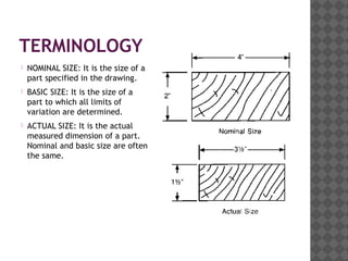
- 2. TERMINOLOGY ’é× NOMINAL SIZE: It is the size of a part specified in the drawing. ’é× BASIC SIZE: It is the size of a part to which all limits of variation are determined. ’é× ACTUAL SIZE: It is the actual measured dimension of a part. Nominal and basic size are often the same.
- 3. LIMIT OF SIZES ’é× There are two extreme possible sizes of a component. ’é× The largest permissible size for a component is called upper limit and smallest size is called lower limit.
- 4. DEVIATION ’é× It is the algebraic difference between any given size and actual size. ’é× ACTUAL DEVIATION: It is the algebraic difference between the actual size and the basic size.
- 5. DEVIATION ’é× LOWER DEVIATION: It is the algebraic difference between the minimum limit of size and the basic size. ’é× UPPER DEVIATION: It is the algebraic difference between the maximum limit and the basic size.
- 6. ZERO LINE ’é× It is the straight line corresponding to the basic size. The deviations are measured from this line.
- 8. NATURAL VARIABILITY OF PROCESS ’é× It is the variation occurred in the size due to natural conditions like variations in material, environmental fluctuations, vibrations, human variability etc. It is an unavoidable process.
- 9. POSITIONAL TOLERANCES ’é× Two types of positional tolerances are used: 1. Unilateral tolerances 2. Bilateral tolerances ’é×’é× When tolerance is on one side of basic size, it is called unilateral and if it is both in plus and minus then it is known as bilateral tolerance.
- 10. FITS ’é× The degree of tightness or looseness between two mating parts is called a fit.
- 11. TYPES OF FITS ’é× CLEARANCE FIT: There is a clearance or looseness in this type of fits. These fits maybe slide fit, easy sliding fit, running fit etc.
- 12. TYPES OF FITS ’é× INTERFERENCE FIT: There is an interference or tightness in these type of fits. E.g. shrink fit, heavy drive fit etc.
- 13. TYPES OF FITS ’é× TRANSITION FIT: In this type of fit, the limits for the mating parts are so selected that either a clearance or interference may occur depending upon the actual size of the mating parts.
- 14. BASIS OF LIMIT SYSTEM 1. HOLE BASIS SYSTEM: In this system, the hole is kept as a constant member and different fits are obtained by varying the shaft size.
- 15. BASIS OF LIMIT SYSTEM ’é× SHAFT BASIS SYSTEM: In this system, the shaft is kept as constant member and different fits are obtained by varying the hole size.
- 16. DIFFERENT LIMIT SYSTEMS 1. The Newall system 2. British Standard system 3. International Federation of National Standardization Association (ISA) system 4. ISO system 5. ISI system
- 17. THE TAYLOR PRINCIPLE TaylorŌĆÖs Principle lays it down: 1. A GO Gauge will check all the dimensions of the work piece in what is called the maximum metal condition (indicating the presence of the greatest amount of material permitted at a prescribed surface) 2. That NOT GO Gauges shall check only one dimension of the work piece at a time, for the minimum metal conditions (indicating the presence of the least amount of material permitted at a prescribed surface) size 28/01/2012lec# 7 & 8 17
- 18. THE TAYLOR PRINCIPLE (Cont..) ’é× In case of hole, the maximum metal condition obtains when the hole is machined to the low limit of size, & minimum metal condition results when the hole is made to the high limit of size. ’é× in case of shaft the limits taken would be inverse of hole
- 19. Thank you


