MODULE-4 Hydrodynamic journal bearing (1).pptx
- 1. MODULE-4 HYDRODYNAMIC JOURNAL BEARING www.cambridge.edu.in Department of Mechanical Engineering TRIBOLOGY 17ME742 MANJUNATHA T V Assistant Professor
- 2. Hydrodynamic journal bearing . www.cambridge.edu.in Department of Mechanical Engineering lightly loaded journal bearing : Friction forces and power loss in a lightly loaded journal bearing, Petroff’s equation, mechanism of pressure development in an oil film, and Reynold’s equation in 2D. Introduction to idealized journal bearing: load carrying capacity, condition for equilibrium, Sommerfeld’s number and it’s significance, partial bearings, end leakages in journal bearing, numerical examples on full journal bearings only.
- 3. Bearings www.cambridge.edu.in Department of Mechanical Engineering A bearing is machine part, which support a moving element and confines its motion. The supporting member is usually designated as bearing and the supporting member may be journal. Since there is a relative motion between the bearing and the moving element, a certain amount of power must be absorbed in overcoming friction, and if the surface actually touches, there will be a rapid wear. Depending upon the nature of contact between the working surfaces:- a) Sliding contact bearings b) Rolling contact bearings.
- 4. Bearing Materials Properties www.cambridge.edu.in Department of Mechanical Engineering a) SLIDING BEARINGS: 1. Hydro dynamically lubricated bearings 2. Bearings with boundary lubrication 3. Bearings with Extreme boundary lubrication. 4. Bearings with Hydrostatic lubrication. b) ROLLING ELEMENT BEARINGS: 1. Ball bearings 2. Roller bearings 3. Needle roller bearings a) BASED ON THE NATURE OF THE LOAD SUPPORTED: 1. Radial bearings - Journal bearings 2. Thrust bearings - Plane thrust bearings - Thrust bearings with fixed shoes - Thrust bearings with Pivoted shoes 3. Bearings for combined Axial and Radial loads. Journal bearing: It is one, which forms the sleeve around the shaft and supports a bearing at right angles to the axis of the bearing. The portion of the shaft resting on the sleeve is called the journal. Example of journal bearings are- Solid bearing , Bushed bearing and Pedestal bearing.
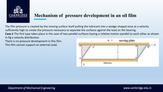
- 5. Mechanism of pressure development in an oil film www.cambridge.edu.in Department of Mechanical Engineering The film pressure is created by the moving surface itself pulling the lubricant into a wedge-shaped zone at a velocity sufficiently high to create the pressure necessary to separate the surfaces against the load on the bearing. Case:1 The first type takes place in the case of two parallel surfaces having a relative motion parallel to each other as shown in fig a velocity distribution. There is no pressure development in this film. This film cannot support an external Load.
- 6. Mechanism of pressure development in an oil film www.cambridge.edu.in Department of Mechanical Engineering Case 2: The second type of velocity distribution across the oil film occurs if pressure exists in the film. This pressure may be developed because of the change of volume between the surfaces so that a lubricant is squeezed out from between the surfaces and the viscous resistance of flow builds up the pressure in the film as shown in Fig . or the pressure may be developed by other means that do not depend upon the motion of the surfaces or it may develop due to the combination of factors. What is important to note here is the fact that pressure in the oil film is always present if the velocity distribution across the oil film is represented by a curved line. Plate AB is stationary while A′ B′ is moving perpendicular to AB. Note that the velocity distribution is Curvilinear. This is a pressure induced flow. This film can support an External load.
- 7. Mechanism of pressure development in an oil film www.cambridge.edu.in Department of Mechanical Engineering  Case 3: Now consider the flow of lubricant through the rectangular areas in section AA’ and BB’ having a width equal to unity in a direction perpendicular to the paper.  The volume of the lubricant that the surface A’B’ tends to carry into the space between the surfaces AB and A’B’ through section AA’ during unit time is AC’A’. The volume of the lubricant that this surface tends to discharge from space through section BB’ during the same period of time is BD’B’. Because the distance AA’ is greater than BB’ the volume AC’A’ is greater than volume BC’B’ by a volume AEC’.  Assuming that the fluid is incompressible and that there is no flow in the direction perpendicular to the motion, the actual volume of oil carried into the space must be equal to the discharge from this space.  Therefore the excess volume of oil is carried into these space is squeezed out through the section AA’ and BB’ producing a constant pressure – induced flow through these sections.
- 8. Mechanism of pressure development in an oil film www.cambridge.edu.in Department of Mechanical Engineering  The actual velocity distribution in section AA’ and BB’ is the result of the combined flow of lubricant due to viscous drag and due to pressure –induced flow. The resultant velocity distributions across these sections are as shown in Fig.  The curve A’NB’ shows the general character of the pressure distribution in the oil film and the line LM shows the mean pressure in the oil film. Because of the pressure developed in the oil film the, plane A’B’ is able to support the vertical load W applied to this plane, preventing metal to metal contact between the surfaces AB and A’B’. This load is equal to the product of projected area of the surface AB and mean pressure in the oil film. Conditions to form hydrodynamic lubrication  There must be a wedge-shaped space between two relative moving plates  There must be a relative sliding velocity between two plates, and the lubricant must flow from big entrance to small exit in the direction of the moving plate  The lubricant should have sufficient viscosity, and the supply of the lubricant is abundant.
- 9. Formation of oil film in a Journal bearing www.cambridge.edu.in Department of Mechanical Engineering  Imagine a journal bearing with a downward load on the shaft that is initially at rest and then brought up to operating speed. At rest (or at slow shaft speeds), the journal will contact the lower face of the bearing as shown in the figure. This condition is known as boundary lubrication and considerable wear can occur.  As shaft speed increases, oil dragged around by the shaft penetrates the gap between the shaft and the bearing so that the shaft begins to float on a film of oil. This is the transition region and is known as thin-film lubrication. The journal may occasionally contact the bearing particularly when shock radial load occur. Moderate wear may occur at these times.  At high speed, the oil film thickness increases until there comes a point where the journal does not contact the bearing at all. This is known as thick film lubrication and no wear occurs because there is no contact between the journal and the bearing.
- 10. Petroff’s Equation for lightly loaded bearing www.cambridge.edu.in Department of Mechanical Engineering  Petroff's Law, is useful because it defines groups of relevant dimensionless parameters, and predicts a fairly accurate coefficient of friction, even when the shaft is not concentric.  The Petroff's equation gives the coefficient of friction in journal bearings.  It assumes that the shaft (journal) and the bushing are concentric.  In reality, the shaft is not concentric with the bearing but the coefficient of friction predicted is quite good.
- 11. www.cambridge.edu.in Department of Mechanical Engineering
- 12. www.cambridge.edu.in Department of Mechanical Engineering
- 13. Sommerfeld number www.cambridge.edu.in Department of Mechanical Engineering  In the design of fluid bearings, the Sommerfeld number (S) is a dimensionless quantity used extensively in hydrodynamic lubrication analysis. The Sommerfeld number is very important in lubrication analysis because it contains all the variables normally specified by the designer. Sommerfeld number is named after Arnold Sommerfeld (1868–1951). The Sommerfeld Number is typically defined by the following equation. Where:  S is the Sommerfeld Number or bearing characteristic number  r is the shaft radius  c is the radial clearance  µ is the absolute viscosity of the lubricant  N is the speed of the rotating shaft in rev/s  P is the load per unit of projected bearing area
- 14. Sommerfeld number www.cambridge.edu.in Department of Mechanical Engineering
- 15. Sommerfeld number www.cambridge.edu.in Department of Mechanical Engineering
- 16. TOWERS EXPERIMENT www.cambridge.edu.in Department of Mechanical Engineering Hydrodynamic lubrication is first discovered in England by Beauchamp Tower (1883). He used a specially constructed test rig for journal bearings simulating the conditions found in railway axle boxes. In order to achieve consistent results, the majority of Tower's investigations were carried out with the shaft immersed into a bath of oil. Tower investigated the influence of lubrication on friction at a high sliding velocity. Like other researchers, he found that the friction coefficient strongly varied with the load and velocity, contrary to what Coulomb had formulated. Dependent on the rotational velocity, a very low friction coefficient of µ=0.001 to 0.01 was found. In the final phase of his research, he decided to drill an oil feed hole in the bearing. During the experiment, the oil was found to rise upwards in the feed hole and leaking over the top of the bearing cap. A wooden plug used to block the hole was pushed out by the oil. He then installed a pressure gauge and found it to be inadequate for measuring the high pressure levels.
- 17. TOWERS EXPERIMENT www.cambridge.edu.in Department of Mechanical Engineering
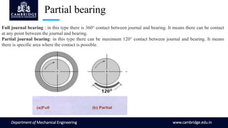
- 18. www.cambridge.edu.in Department of Mechanical Engineering Full journal bearing : in this type there is 360° contact between journal and bearing. It means there can be contact at any point between the journal and bearing. Partial journal bearing: in this type there can be maximum 120° contact between journal and bearing. It means there is specific area where the contact is possible. Partial bearing
- 19. PARTIAL BEARING 180 and 360 degree www.cambridge.edu.in Department of Mechanical Engineering
- 20. PARTIAL BEARING 120 and 180 degree with µ/ψ www.cambridge.edu.in Department of Mechanical Engineering
- 21. PARTIAL BEARING 60 and 120 DEGREE www.cambridge.edu.in Department of Mechanical Engineering
- 22. PIVOT BEARING www.cambridge.edu.in Department of Mechanical Engineering
- 23. www.cambridge.edu.in Department of Mechanical Engineering Thank you

