

module-2.pptx
- 1. ÔÇ£Module 2ÔÇØ 8051 Microcontroller Architecture
- 2. Module 2 : 8051 microcontroller architecture: Microcontrollers and embedded systems, 8051 microcontroller family, 8051 architecture, Pin diagram of 8051, memory organization of 8051
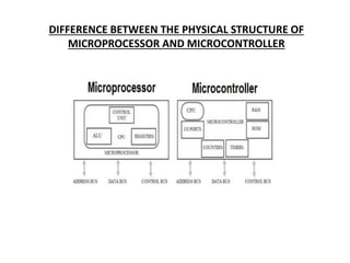
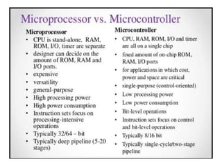
- 3. DIFFERENCE BETWEEN THE PHYSICAL STRUCTURE OF MICROPROCESSOR AND MICROCONTROLLER
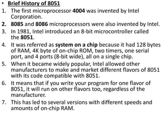
- 5. ÔÇó Brief History of 8051 1. The first microprocessor 4004 was invented by Intel Corporation. 2. 8085 and 8086 microprocessors were also invented by Intel. 3. In 1981, Intel introduced an 8-bit microcontroller called the 8051. 4. It was referred as system on a chip because it had 128 bytes of RAM, 4K byte of on-chip ROM, two timers, one serial port, and 4 ports (8-bit wide), all on a single chip. 5. When it became widely popular, Intel allowed other manufacturers to make and market different flavors of 8051 with its code compatible with 8051. 6. It means that if you write your program for one flavor of 8051, it will run on other flavors too, regardless of the manufacturer. 7. This has led to several versions with different speeds and amounts of on-chip RAM.
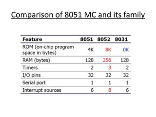
- 6. Comparison of 8051 MC and its family
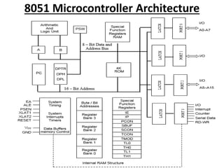
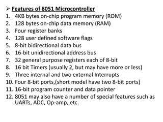
- 8. ´âÿ Features of 8051 Microcontroller 1. 4KB bytes on-chip program memory (ROM) 2. 128 bytes on-chip data memory (RAM) 3. Four register banks 4. 128 user defined software flags 5. 8-bit bidirectional data bus 6. 16-bit unidirectional address bus 7. 32 general purpose registers each of 8-bit 8. 16 bit Timers (usually 2, but may have more or less) 9. Three internal and two external Interrupts 10. Four 8-bit ports,(short model have two 8-bit ports) 11. 16-bit program counter and data pointer 12. 8051 may also have a number of special features such as UARTs, ADC, Op-amp, etc.
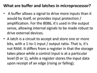
- 9. What are buffer and latches in microprocessor? ÔÇó A buffer allows a signal to drive more inputs than it would by itself, or provides input protection / amplification. For the 8086, it's used in the output sense, allowing internal signals to be made robust to drive external devices. ÔÇó A latch is a circuit to accept and store one or more bits, with a 1-to-1 input / output ratio. That is, it's not RAM. It differs from a register in that the storage takes place while a control input is at a particular level (0 or 1), while a register stores the input data upon receipt of an edge (rising or falling).
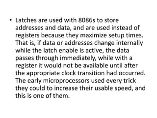
- 10. ÔÇó Latches are used with 8086s to store addresses and data, and are used instead of registers because they maximize setup times. That is, if data or addresses change internally while the latch enable is active, the data passes through immediately, while with a register it would not be available until after the appropriate clock transition had occurred. The early microprocessors used every trick they could to increase their usable speed, and this is one of them.
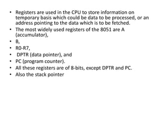
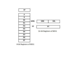
- 11. ÔÇó Registers are used in the CPU to store information on temporary basis which could be data to be processed, or an address pointing to the data which is to be fetched. ÔÇó The most widely used registers of the 8051 are A (accumulator), ÔÇó B, ÔÇó R0-R7, ÔÇó DPTR (data pointer), and ÔÇó PC (program counter). ÔÇó All these registers are of 8-bits, except DPTR and PC. ÔÇó Also the stack pointer
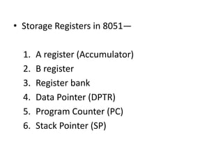
- 12. ÔÇó Storage Registers in 8051ÔÇö 1. A register (Accumulator) 2. B register 3. Register bank 4. Data Pointer (DPTR) 5. Program Counter (PC) 6. Stack Pointer (SP)
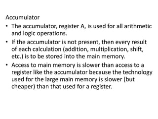
- 13. Accumulator ÔÇó The accumulator, register A, is used for all arithmetic and logic operations. ÔÇó If the accumulator is not present, then every result of each calculation (addition, multiplication, shift, etc.) is to be stored into the main memory. ÔÇó Access to main memory is slower than access to a register like the accumulator because the technology used for the large main memory is slower (but cheaper) than that used for a register.
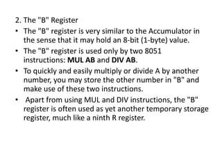
- 14. 2. The "B" Register ÔÇó The "B" register is very similar to the Accumulator in the sense that it may hold an 8-bit (1-byte) value. ÔÇó The "B" register is used only by two 8051 instructions: MUL AB and DIV AB. ÔÇó To quickly and easily multiply or divide A by another number, you may store the other number in "B" and make use of these two instructions. ÔÇó Apart from using MUL and DIV instructions, the "B" register is often used as yet another temporary storage register, much like a ninth R register.
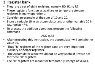
- 15. 3. Register bank  They are a set of eight registers, namely, R0, R1 to R7.  These registers function as auxiliary or temporary storage registers in many operations.  Consider an example of the sum of 10 and 20.  Store a variable 10 in an accumulator and another variable 20 in, say, register R4.  To process the addition operation, execute the following command  ADD A,R4  After executing this instruction, the accumulator will contain the value 30.  Thus "R" registers of the register bank are very important auxiliary or helper registers.  The Accumulator alone would not be very useful if it were not for these "R" registers.  The "R" registers are meant for temporarily storage of values.
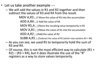
- 16. ÔÇó Let us take another example --- ÔÇô We will add the values in R1 and R2 together and then subtract the values of R3 and R4 from the result. MOV A,R3 ; // Move the value of R3 into the accumulator ADD A,R4 ; // Add the value of R4 MOV R5,A ; //Store the resulting value temporarily in R5 MOV A,R1 ; //Move the value of R1 into the accumulator ADD A,R2 ; //Add the value of R2 SUBB A,R5 ; //Subtract the value of R5 (which now contains R3 + R4) ÔÇô As you can see, we used R5 to temporarily hold the sum of R3 and R4. ÔÇô Of course, this is not the most efficient way to calculate (R1 + R2) ÔÇô (R3 + R4), but it does illustrate the use of the "R" registers as a way to store values temporarily.
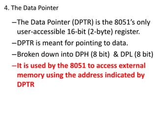
- 18. 4. The Data Pointer ÔÇôThe Data Pointer (DPTR) is the 8051ÔÇÖs only user-accessible 16-bit (2-byte) register. ÔÇôDPTR is meant for pointing to data. ÔÇôBroken down into DPH (8 bit) & DPL (8 bit) ÔÇôIt is used by the 8051 to access external memory using the address indicated by DPTR
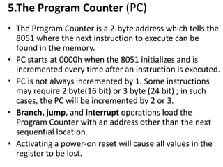
- 19. 5.The Program Counter (PC) ÔÇó The Program Counter is a 2-byte address which tells the 8051 where the next instruction to execute can be found in the memory. ÔÇó PC starts at 0000h when the 8051 initializes and is incremented every time after an instruction is executed. ÔÇó PC is not always incremented by 1. Some instructions may require 2 byte(16 bit) or 3 byte (24 bit) ; in such cases, the PC will be incremented by 2 or 3. ÔÇó Branch, jump, and interrupt operations load the Program Counter with an address other than the next sequential location. ÔÇó Activating a power-on reset will cause all values in the register to be lost.
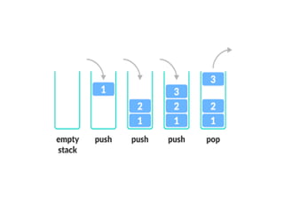
- 20. -- What is stack? ´éº A stack is an array-like structure in the memory in which data can be stored and removed from a location called the 'top' of the stack. ´éº The data that needs to be stored is 'pushed' into the stack and data to be retrieved is 'popped' out from the stack.
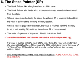
- 22. 6. The Stack Pointer (SP) ÔÇô The Stack Pointer, like all registers hold an 8-bit value. ÔÇô The Stack Pointer tells the location from where the next value is to be removed from the stack. ÔÇô When a value is pushed onto the stack, the value of SP is incremented and then the value is stored at the resulting memory location. ÔÇô When a value is popped off the stack, the value is returned from the memory location indicated by SP, and then the value of SP is decremented. ÔÇô This order of operation is important. First PUSH & then POP ÔÇô SP will be initialized to 07h when the 8051 is initialized (on start up). If a value is pushed onto the stack at the same time, the value will be stored in the internal RAM address 08h because the 8051 will first increment the value of SP (from 07h to 08h) and then will store the pushed value at that memory address (08h). ÔÇô SP is modified directly by the 8051 by six instructions: PUSH, POP, ACALL, LCALL, RET, and RETI.
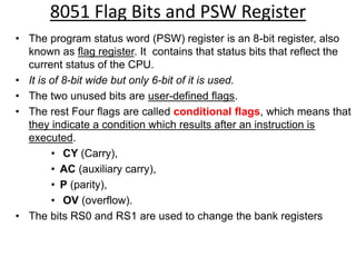
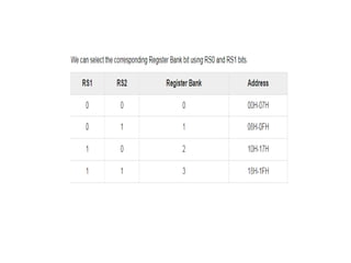
- 23. 8051 Flag Bits and PSW Register ÔÇó The program status word (PSW) register is an 8-bit register, also known as flag register. It contains that status bits that reflect the current status of the CPU. ÔÇó It is of 8-bit wide but only 6-bit of it is used. ÔÇó The two unused bits are user-defined flags. ÔÇó The rest Four flags are called conditional flags, which means that they indicate a condition which results after an instruction is executed. ÔÇó CY (Carry), ÔÇó AC (auxiliary carry), ÔÇó P (parity), ÔÇó OV (overflow). ÔÇó The bits RS0 and RS1 are used to change the bank registers
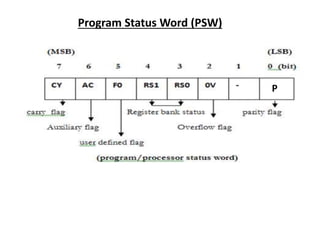
- 24. Program Status Word (PSW) P
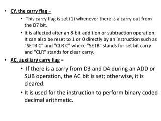
- 26.  CY, the carry flag   This carry flag is set (1) whenever there is a carry out from the D7 bit.  It is affected after an 8-bit addition or subtraction operation. It can also be reset to 1 or 0 directly by an instruction such as "SETB C" and "CLR C" where "SETB" stands for set bit carry and "CLR" stands for clear carry.  AC, auxiliary carry flag   If there is a carry from D3 and D4 during an ADD or SUB operation, the AC bit is set; otherwise, it is cleared.  It is used for the instruction to perform binary coded decimal arithmetic.
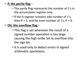
- 27.  P, the parity flag   The parity flag represents the number of 1's in the accumulator register only.  If the A register contains odd number of 1's, then P = 1; and for even number of 1's, P = 0.  OV, the overflow flag   This flag is set whenever the result of a signed number operation is too large causing the high-order bit to overflow into the sign bit.  It is used only to detect errors in signed arithmetic operations.
- 28. Example ÔÇó Show the status of CY, AC, and P flags after the addition of 9CH and 64H in the following instruction. MOV A, #9CH ADD A, # 64H
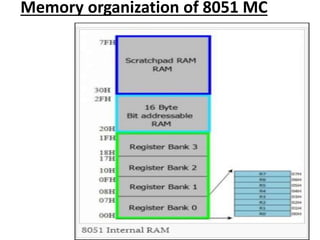
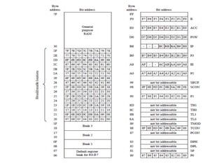
- 29. Memory organization of 8051 MC
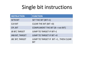
- 31. Single bit instructions INSTRUCTION FUNCTION SETB BIT SET THE BIT (BIT=1) CLR BIT CLEAR THE BIT (BIT =0) CPL BIT COMPLIMENT THE BIT (B = not BIT) JB BIT, TARGET JUMP TO TARGET IF BIT=1 JNB BIT, TARGET JUMP TO TARGET IF BIT =0 JBC BIT, TARGET JUMP TO TARGET IF BIT =1 , THEN CLEAR BIT
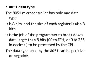
- 32. ÔÇó 8051 data type The 8051 microcontroller has only one data type. It is 8 bits, and the size of each register is also 8 bits. It is the job of the programmer to break down data larger than 8 bits (00 to FFH, or 0 to 255 in decimal) to be processed by the CPU. The data type used by the 8051 can be positive or negative.
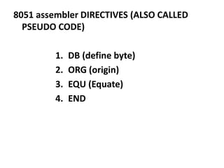
- 33. 8051 assembler DIRECTIVES (ALSO CALLED PSEUDO CODE) 1. DB (define byte) 2. ORG (origin) 3. EQU (Equate) 4. END
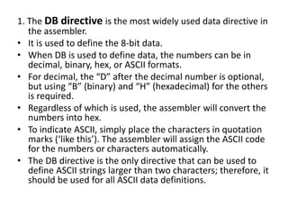
- 34. 1. The DB directive is the most widely used data directive in the assembler. ÔÇó It is used to define the 8-bit data. ÔÇó When DB is used to define data, the numbers can be in decimal, binary, hex, or ASCII formats. ÔÇó For decimal, the ÔÇ£DÔÇØ after the decimal number is optional, but using ÔÇ£BÔÇØ (binary) and ÔÇ£HÔÇØ (hexadecimal) for the others is required. ÔÇó Regardless of which is used, the assembler will convert the numbers into hex. ÔÇó To indicate ASCII, simply place the characters in quotation marks (ÔÇÿlike thisÔÇÖ). The assembler will assign the ASCII code for the numbers or characters automatically. ÔÇó The DB directive is the only directive that can be used to define ASCII strings larger than two characters; therefore, it should be used for all ASCII data definitions.
- 36. 2. ORG (origin) ÔÇó The ORG directive is used to indicate the beginning of the address. The number that comes after ORG can be either in hex or in decimal. If the number is not followed by H, it is decimal and the assembler will convert it to hex
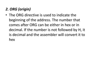
- 37. 3. EQU (equate) This is used to define a constant without occupying a memory location. The EQU directive does not set aside storage for a data item but associates a constant value with a data label so that when the label appears in the program, its constant value will be substituted for the label. The following uses EQU for the counter constant and then the constant is used to load the R3 register.
- 38. When executing the instruction ÔÇ£MOV R3, #COUNTÔÇØ, the register R3 will be loaded with the value 25 (notice the # sign). What is the advantage of using EQU? Assume that there is a constant (a fixed value) used in many different places in the program, and the programmer wants to change its value throughout. By the use of EQU, the programmer can change it once and the assembler will change all of its occurrences, rather than search the entire program trying to find every occurrence.
- 39. 4.END directive ÔÇó This indicates to the assembler the end of the source (asm) file. ÔÇó The END directive is the last line of an 8051 program, meaning that in the source code anything after the END directive is ignored by the assembler.
- 40. ÔÇó What are label in ALP? Labels are used to name the entry point of a subroutine, to name the beginning of some data, to name points in the code for construction of control flow constructs
- 41. ´âÿRules for labels in Assembly language 1. First, each label name must be unique. 2. The names used for labels in Assembly language programming consist of alphabetic letters in both uppercase and lowercase, the digits 0 through 9, and the special characters question mark (?), period (.), at (@), underline (_), and dollar sign ($). 3. The first character of the label must be an alphabetic character. In other words it cannot be a number. 4. Every assembler has some reserved words that must not be used as labels in the program. 5. For example, ÔÇ£MOVÔÇØ and ÔÇ£ADDÔÇØ are reserved since they are instruction mnemonics. And cannot be names of register or instruction used in 8051 programming
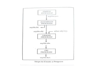
- 42. NOTES: --- 1 Assembler An assembler translates assembly language programs into machine code. The output of an assembler is called an object file, which contains a combination of machine instructions as well as the data required to place these instructions in memory. 2 Linker Linker is a computer program that links and merges various object files together in order to make an executable file. All these files might have been compiled by separate assemblers. The major task of a linker is to search and locate referenced module/routines in a program and to determine the memory location where these codes will be loaded, making the program instruction to have absolute references.
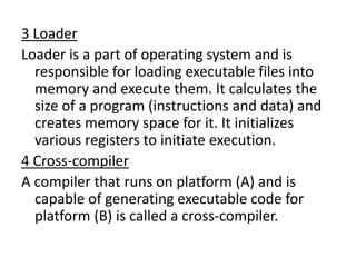
- 43. 3 Loader Loader is a part of operating system and is responsible for loading executable files into memory and execute them. It calculates the size of a program (instructions and data) and creates memory space for it. It initializes various registers to initiate execution. 4 Cross-compiler A compiler that runs on platform (A) and is capable of generating executable code for platform (B) is called a cross-compiler.
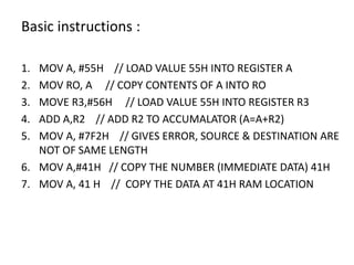
- 45. Basic instructions : 1. MOV A, #55H // LOAD VALUE 55H INTO REGISTER A 2. MOV RO, A // COPY CONTENTS OF A INTO RO 3. MOVE R3,#56H // LOAD VALUE 55H INTO REGISTER R3 4. ADD A,R2 // ADD R2 TO ACCUMALATOR (A=A+R2) 5. MOV A, #7F2H // GIVES ERROR, SOURCE & DESTINATION ARE NOT OF SAME LENGTH 6. MOV A,#41H // COPY THE NUMBER (IMMEDIATE DATA) 41H 7. MOV A, 41 H // COPY THE DATA AT 41H RAM LOCATION
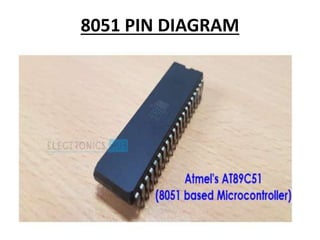
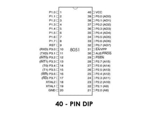
- 46. 8051 PIN DIAGRAM
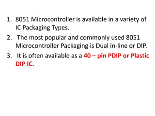
- 47. 1. 8051 Microcontroller is available in a variety of IC Packaging Types. 2. The most popular and commonly used 8051 Microcontroller Packaging is Dual in-line or DIP. 3. It is often available as a 40 ÔÇô pin PDIP or Plastic DIP IC.
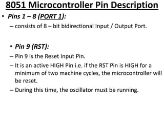
- 49. 8051 Microcontroller Pin Description ÔÇó Pins 1 ÔÇô 8 (PORT 1): ÔÇô consists of 8 ÔÇô bit bidirectional Input / Output Port. ÔÇó Pin 9 (RST): ÔÇô Pin 9 is the Reset Input Pin. ÔÇô It is an active HIGH Pin i.e. if the RST Pin is HIGH for a minimum of two machine cycles, the microcontroller will be reset. ÔÇô During this time, the oscillator must be running.
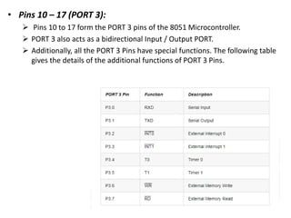
- 50. ÔÇó Pins 10 ÔÇô 17 (PORT 3): ´âÿ Pins 10 to 17 form the PORT 3 pins of the 8051 Microcontroller. ´âÿ PORT 3 also acts as a bidirectional Input / Output PORT. ´âÿ Additionally, all the PORT 3 Pins have special functions. The following table gives the details of the additional functions of PORT 3 Pins.
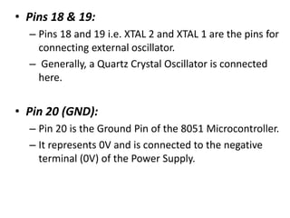
- 51. ÔÇó Pins 18 & 19: ÔÇô Pins 18 and 19 i.e. XTAL 2 and XTAL 1 are the pins for connecting external oscillator. ÔÇô Generally, a Quartz Crystal Oscillator is connected here. ÔÇó Pin 20 (GND): ÔÇô Pin 20 is the Ground Pin of the 8051 Microcontroller. ÔÇô It represents 0V and is connected to the negative terminal (0V) of the Power Supply.
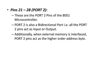
- 52. ÔÇó Pins 21 ÔÇô 28 (PORT 2): ÔÇô These are the PORT 2 Pins of the 8051 Microcontroller. ÔÇô PORT 2 is also a Bidirectional Port i.e. all the PORT 2 pins act as Input or Output. ÔÇô Additionally, when external memory is interfaced, PORT 2 pins act as the higher order address byte.
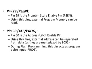
- 53. ÔÇó Pin 29 (PSEN): ÔÇô Pin 29 is the Program Store Enable Pin (PSEN). ÔÇô Using this pins, external Program Memory can be read. ÔÇó Pin 30 (ALE/PROG): ÔÇô Pin 30 is the Address Latch Enable Pin. ÔÇô Using this Pins, external address can be separated from data (as they are multiplexed by 8051). ÔÇô During Flash Programming, this pin acts as program pulse input (PROG).
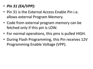
- 54. ÔÇó Pin 31 (EA/VPP): ÔÇó Pin 31 is the External Access Enable Pin i.e. allows external Program Memory. ÔÇó Code from external program memory can be fetched only if this pin is LOW. ÔÇó For normal operations, this pins is pulled HIGH. ÔÇó During Flash Programming, this Pin receives 12V Programming Enable Voltage (VPP).
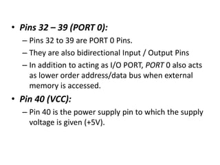
- 55. ÔÇó Pins 32 ÔÇô 39 (PORT 0): ÔÇô Pins 32 to 39 are PORT 0 Pins. ÔÇô They are also bidirectional Input / Output Pins ÔÇô In addition to acting as I/O PORT, PORT 0 also acts as lower order address/data bus when external memory is accessed. ÔÇó Pin 40 (VCC): ÔÇô Pin 40 is the power supply pin to which the supply voltage is given (+5V).
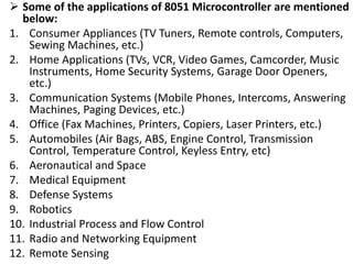
- 56. ´âÿ Some of the applications of 8051 Microcontroller are mentioned below: 1. Consumer Appliances (TV Tuners, Remote controls, Computers, Sewing Machines, etc.) 2. Home Applications (TVs, VCR, Video Games, Camcorder, Music Instruments, Home Security Systems, Garage Door Openers, etc.) 3. Communication Systems (Mobile Phones, Intercoms, Answering Machines, Paging Devices, etc.) 4. Office (Fax Machines, Printers, Copiers, Laser Printers, etc.) 5. Automobiles (Air Bags, ABS, Engine Control, Transmission Control, Temperature Control, Keyless Entry, etc) 6. Aeronautical and Space 7. Medical Equipment 8. Defense Systems 9. Robotics 10. Industrial Process and Flow Control 11. Radio and Networking Equipment 12. Remote Sensing
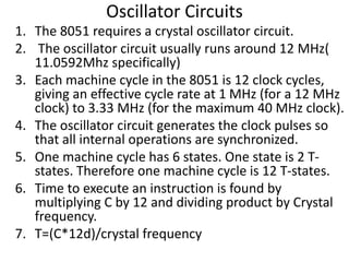
- 57. Oscillator Circuits 1. The 8051 requires a crystal oscillator circuit. 2. The oscillator circuit usually runs around 12 MHz( 11.0592Mhz specifically) 3. Each machine cycle in the 8051 is 12 clock cycles, giving an effective cycle rate at 1 MHz (for a 12 MHz clock) to 3.33 MHz (for the maximum 40 MHz clock). 4. The oscillator circuit generates the clock pulses so that all internal operations are synchronized. 5. One machine cycle has 6 states. One state is 2 T- states. Therefore one machine cycle is 12 T-states. 6. Time to execute an instruction is found by multiplying C by 12 and dividing product by Crystal frequency. 7. T=(C*12d)/crystal frequency
- 59. MACHINE CYCLE CALCULATION FORMULA :--- MACHINE CYCLE FREQUENCY = 1/12 XTAL 1.FIND THE MACHINE CYCLE FORÔÇö a) XTAL = 11.0592 MHz = 1.085 microsec b) XTAL = 16 MHz = 0.75 microsec