MP5040 Lecture 11,12.pdf- distillation process
- 1. MP5040: PROCESS ENGINEERING Lecturer: Miss. J Sajeeva Lecture Number 11
- 2. QUESTION A solute A is to be recovered from an inert carrier gas B by absorption into a solvent. The gas entering into the absorber flows at a rate of 500 kmol/h with ð¦ð´ = 0.3 and leaving the absorber with ð¦ð´ = 0.01. Solvent enters the absorber at the rate of 1500 kmol/h with ð¥ð´ =0.001. The equilibrium relationship is ð¦ð´ = 2.8 ð¥ð´ . The carrier gas may be considered insoluble in the solvent and the solvent may be considered nonvolatile. 1. Determine the à´¤ ð¿ and à´¤ ð 2. Find out the operation line 3. Construct the x-y plots for the equilibrium and operating lines using both mole fraction and solute-free coordinates à´¥ ðð¨ = à´¤ ð³ à´¥ ð½ à´¥ ð¿ð¨ + (à´¥ ðð¨ð â à´¤ ð³ à´¥ ð½ à´¥ ð¿ð¨ð)
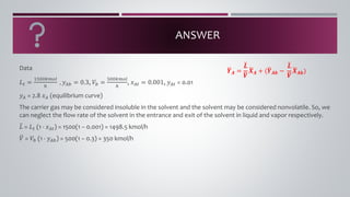
- 3. ANSWER Data ð¿ð¡ = 1500ðððð â , ð¦ð´ð = 0.3, ðð = 500ðððð â , ð¥ð´ð¡ = 0.001, ð¦ð´ð¡ = 0.01 ð¦ð´ = 2.8 ð¥ð´ (equilibrium curve) The carrier gas may be considered insoluble in the solvent and the solvent may be considered nonvolatile. So, we can neglect the flow rate of the solvent in the entrance and exit of the solvent in liquid and vapor respectively. à´¤ ð¿ = ð¿ð¡ (1 - ð¥ð´ð¡) = 1500(1 â 0.001) = 1498.5 kmol/h à´¤ ð = ðð (1 - ð¦ð´ð) = 500(1 â 0.3) = 350 kmol/h à´¥ ðð¨ = à´¤ ð³ à´¥ ð½ à´¥ ð¿ð¨ + (à´¥ ðð¨ð â à´¤ ð³ à´¥ ð½ à´¥ ð¿ð¨ð)
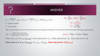
- 4. ANSWER ð¿ð¡ = 1500ðððð â , ð¦ð´ð = 0.3, ðð = 500ðððð â , ð¥ð´ð¡ = 0.001, ð¦ð´ð¡ = 0.01 à´¤ ð¿ = 1498.5 kmol/h à´¤ ð = 350 kmol/h The concentration of A in the solvent stream leaving the absorber can be determined from the following expressions: ð¥ð´ð = ð¹ððð¤ ððð¡ð ðð ð´ ðð ð¿ð ð¹ððð¤ ððð¡ð ðð ð´ ðð ð¿ð+à´¤ ð¿ ð¹ððð¤ ððð¡ð ðð ð´ ðð ð¿ð (ð¿ðð¥ð´ð) = Flow rate of A in ð¿ð¡ + Flow rate of A in ðð - Flow rate of A in ðð¡ ð¹ððð¤ ððð¡ð ðð ð´ ðð ð¿ð (ð¿ðð¥ð´ð) = ð¿ð¡ ð¥ð´ð¡ + ððð¦ð´ð- Flow rate of A in ð½ð(ðð¡ð¦ð´ð¡) à´¤ ðð´ð = ð¥ð´ð (1 â ð¥ð´ð) à´¤ ð ð´ð = ð¦ð´ð (1 â ð¦ð´ð) à´¤ ð ð´ = à´¤ ð¿ à´¤ ð à´¤ ðð´ + (à´¤ ð ð´ð â à´¤ ð¿ à´¤ ð à´¤ ðð´ð) ð¿ðð¥ð´ð + ðð¡ð¦ð´ð¡ = ð¿ð¡ð¥ð´ð¡ + ððð¦ð´ð
- 5. ANSWER But ð¦ð´ð¡ = ðððð ðððð ðð ð¨ ðð ð½ð ðððð ðððð ðð ð¨ ðð ð½ð+à´¥ ð = 0.01 ðððð ðððð ðð ð¨ ðð ð½ð = 3.5354 kmol/h
- 6. ANSWER Determine 1. à´¥ ðð¨ð 2. à´¥ ð¿ð¨ð à´¤ ðð´ = ð¥ð´ (1âð¥ð´) = ðððð ððððð¡ððð ðð ð´ ðð ð¡âð ðððð¢ðð ðððð ððððð¡ððð ðð ððð ð´ ððððððððð¡ð ðð ð¡âð ðððð¢ðð à´¤ ð ð´ = ð¦ð´ (1âð¦ð´) = ðððð ððððð¡ððð ðð ð´ ðð ð¡âð ð£ðððð ðððð ððððð¡ððð ðð ððð ð´ ððððððððð¡ð ðð ð¡âð ð£ðððð à´¤ ð ð´ = à´¤ ð¿ à´¤ ð à´¤ ðð´ + (à´¤ ð ð´ð â à´¤ ð¿ à´¤ ð à´¤ ðð´ð) 0.4286,0.0987
- 7. EQUILIBRIUM CURVE The equilibrium curves in both mole fraction and solute-free coordinates are calculated from the following procedures: 1. ð¶âððð ð ð ð£ððð¢ð ðð ð¥ð´ ððð¡ð¤ððð 0.001 ððð 0.10 2. ð¸ð£ððð¢ðð¡ð ð¡âð ðððððð ððððððð à´¤ ðð´ = ð¥ð´ (1âð¥ð´) 3. ð¸ð£ððð¢ðð¡ð ð¦ð´ = 2.8 ð¥ð´ 4. ð¸ð£ððð¢ðð¡ð ð¡âð ðððððð ððððððð à´¤ ð ð´ = ð¦ð´ (1âð¦ð´) ð¥ð´ à´¤ ðð´ ð¦ð´ à´¤ ð ð´
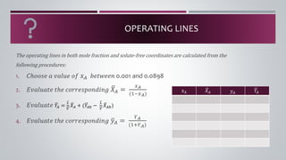
- 8. OPERATING LINES The operating lines in both mole fraction and solute-free coordinates are calculated from the following procedures: 1. ð¶âððð ð ð ð£ððð¢ð ðð ð¥ð´ ððð¡ð¤ððð 0.001 and 0.0898 2. ð¸ð£ððð¢ðð¡ð ð¡âð ðððððð ððððððð à´¤ ðð´ = ð¥ð´ (1âð¥ð´) 3. ð¸ð£ððð¢ðð¡ð à´¤ ð ð´ = à´¤ ð¿ à´¥ ð à´¤ ðð´ + (à´¤ ð ð´ð â à´¤ ð¿ à´¥ ð à´¤ ðð´ð) 4. ð¸ð£ððð¢ðð¡ð ð¡âð ðððððð ððððððð à´¤ ð¦ð´ = ðð´ (1+ðð´) ð¥ð´ à´¤ ðð´ ð¦ð´ à´¤ ð ð´
- 9. EQUILIBRIUM CURVE The equilibrium curves in both mole fraction and solute-free coordinates are calculated from the following procedures: 1. ð¶âððð ð ð ð£ððð¢ð ðð ð¥ð´ ððð¡ð¤ððð 0.001 ððð 0.10 2. ð¸ð£ððð¢ðð¡ð ð¡âð ðððððð ððððððð à´¤ ðð´ = ð¥ð´ (1âð¥ð´) 3. ð¸ð£ððð¢ðð¡ð ð¦ð´ = 2.8 ð¥ð´ 4. ð¸ð£ððð¢ðð¡ð ð¡âð ðððððð ððððððð à´¤ ð ð´ = ð¦ð´ (1âð¦ð´) ð¥ð´ à´¤ ðð´ ð¦ð´ à´¤ ð ð´
- 10. OPERATING LINES The operating lines in both mole fraction and solute-free coordinates are calculated from the following procedures: 1. ð¶âððð ð ð ð£ððð¢ð ðð ð¥ð´ ððð¡ð¤ððð 0.001 and 0.0898 2. ð¸ð£ððð¢ðð¡ð ð¡âð ðððððð ððððððð à´¤ ðð´ = ð¥ð´ (1âð¥ð´) 3. ð¸ð£ððð¢ðð¡ð à´¤ ð ð´ = à´¤ ð¿ à´¥ ð à´¤ ðð´ + (à´¤ ð ð´ð â à´¤ ð¿ à´¥ ð à´¤ ðð´ð) 4. ð¸ð£ððð¢ðð¡ð ð¡âð ðððððð ððððððð à´¤ ð¦ð´ = ðð´ (1+ðð´) ð¥ð´ à´¤ ðð´ ð¦ð´ à´¤ ð ð´
- 11. PLOT THE GRAPHS
- 12. ï¡ The driving force for mass transfer becomes zero whenever the operating line intersects or touches the equilibrium curve. ï¡ This limiting condition represents the minimum solvent rate to recover a specified quantity of solute or the solvent rate required to remove the maximum amount of solute. LIMITING CONDITIONS FOR ABSORPTION PROCESS.
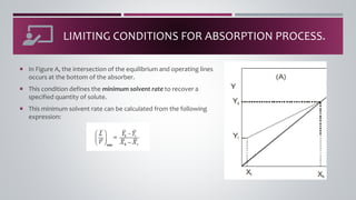
- 13. ï¡ In Figure A, the intersection of the equilibrium and operating lines occurs at the bottom of the absorber. ï¡ This condition defines the minimum solvent rate to recover a specified quantity of solute. ï¡ This minimum solvent rate can be calculated from the following expression: LIMITING CONDITIONS FOR ABSORPTION PROCESS.
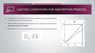
- 14. ï¡ In Figure B, the intersection of the equilibrium and operating lines occurs at the top of the absorber. ï¡ This condition represents the solvent rate required to remove the maximum amount of solute. ï¡ This solvent rate can be calculated from the following expression: LIMITING CONDITIONS FOR ABSORPTION PROCESS.
- 15. BASIC PROCESS OPERATIONS DISTILLATION PROCESS
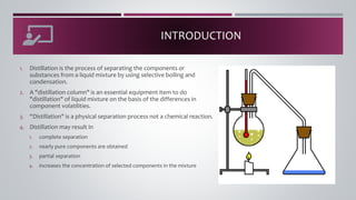
- 17. INTRODUCTION 1. Distillation is the process of separating the components or substances from a liquid mixture by using selective boiling and condensation. 2. A "distillation column" is an essential equipment item to do "distillation" of liquid mixture on the basis of the differences in component volatilities. 3. âDistillation" is a physical separation process not a chemical reaction. 4. Distillation may result in 1. complete separation 2. nearly pure components are obtained 3. partial separation 4. increases the concentration of selected components in the mixture
- 18. SUGGEST ANY DAILY ACTIVITIES THAT ARE USING DISTILLATION PROCESS
- 19. APPLICATION 1. The earliest known evidence of "distillationâ comes from a "terracotta distillation" apparatus dating to 3000 bc in the "Indus valley civilization" 2. Initially "distillation" is believed to have been used to make perfumes / distillation of alcoholic beverages occurred. 3. As far as industrial application is concerned distillation is used for many commercial processes such as the production of gasoline, distilled water, xylene, alcohol, paraffin, kerosene and many other liquids 4. Gas may be liquefied and separated it is called as "cryogenic distillationâ For example: nitrogen, oxygen and argon are distilled from air.
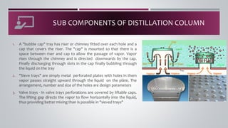
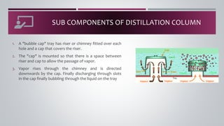
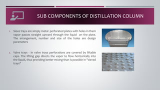
- 20. SUB COMPONENTS OF DISTILLATION COLUMN 1. A "bubble cap" tray has riser or chimney fitted over each hole and a cap that covers the riser. The "cap" is mounted so that there is a space between riser and cap to allow the passage of vapor. Vapor rises through the chimney and is directed downwards by the cap. Finally discharging through slots in the cap finally bubbling through the liquid on the tray 2. "Sieve trays" are simply metal perforated plates with holes in them vapor passes straight upward through the liquid on the plate. The arrangement, number and size of the holes are design parameters 3. Valve trays - In valve trays perforations are covered by liftable caps. The lifting gap directs the vapor to flow horizontally into the liquid, thus providing better mixing than is possible in "sieved trays"
- 21. SUB COMPONENTS OF DISTILLATION COLUMN 1. A "bubble cap" tray has riser or chimney fitted over each hole and a cap that covers the riser. 2. The "cap" is mounted so that there is a space between riser and cap to allow the passage of vapor. 3. Vapor rises through the chimney and is directed downwards by the cap. Finally discharging through slots in the cap finally bubbling through the liquid on the tray
- 22. SUB COMPONENTS OF DISTILLATION COLUMN 1. Sieve trays are simply metal perforated plates with holes in them vapor passes straight upward through the liquid on the plate. The arrangement, number and size of the holes are design parameters 2. Valve trays - In valve trays perforations are covered by liftable caps. The lifting gap directs the vapor to flow horizontally into the liquid, thus providing better mixing than is possible in "sieved trays"
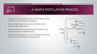
- 23. MAIN COMPONENTS OF DISTILLATION COLUMN 1. Distillation columns are made up of several components. Each of which is used either to 1. transfer heat energy 2. enhance material transfer 2. A schematic of a typical distillation unit with a single feed and two product streams is shown. 3. A vertical shell where the separation of liquid components is carried out. 4. Column internal such as trays, plates and packings which are used to enhance component separations. 5. A reboiler to provide the necessary vaporization for the distillation process 6. A condenser to cool and condense the vapor leaving the top of the column 7. A reflux drum to hold the condensed vapor from the top of the column, so that liquid reflux can be recycled back to the column. 8. Receivers are used to store the outputs from top and bottom of the column
- 24. A SIMPLE DISTILLATION PROCESS 1. Liquid mixture that is to be processed is known as the feed and this is introduced usually somewhere near the middle of the column to a tray known as the "feed trayâ. 2. The feed tray divides the column into a top enriching our rectification section and a bottom that is "stripping sectionâ. 3. The feed flows down the column where it is collected at the bottom in the reboiler heat is supplied to the reboiler to generate vapor. The source of heat input can be any suitable fluid Although in most chemical plants this is normally steam. 4. The vapor raised in the reboiler is reintroduced into the unit at the bottom of the column. The liquid removed from the reboiler is known as the bottoms product.
- 25. A SIMPLE DISTILLATION PROCESS 5. The vapor moves up the column and as it exits the top of the unit it is cooled by a condenser. 6. The condensed liquid is stored in a holding vessel known as the reflux drum. 7. Some of this liquid is recycled back to the top of the column and this is called the reflux. 8. The condensed liquid that is removed from the system is known as the "distillate or top product".
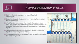
- 26. A SIMPLE DISTILLATION PROCESS â Each tray has 2 conduits, one on each side, called DOWNCOMER â Liquid falls through the downcomers by gravity from one tray to the one below it. â A WEIR on the tray ensures that there is always some liquid (HOLDUP) on the tray and is designed such that the holdup is at a suitable height, e.g. such that the bubble caps are covered by liquid. â Vapor flows up the column and is forced to pass through the liquid, via the openings on each tray. â The area allowed for the passage of vapor on each tray is called the "active tray area"
