This document summarizes the design calculations for section 1 of a mechanically stabilized earth (MSE) wall. It analyzes the external stability including sliding resistance, overturning, and bearing capacity. It also evaluates the internal stability, checking the pullout and tensile resistance of the soil reinforcements. The calculations show the wall design satisfies factors of safety for different load cases, indicating the section 1 panel arrangement and reinforcement design is adequate.
Worked Examples for Timber Beam Design to AS1720.1 WebinarClearCalcs
Ìý
This document analyzes a timber beam used as a floor bearer. It summarizes the demands on the beam from different load cases, including moment, shear, bearing and deflection. The governing load cases are identified as 1.2G, 1.5Q for moment, shear and bearing demands. Short-term deflection is governed by load case G, Q_st, while long-term deflection is governed by G, Q_lt. The beam properties, load cases, demands and capacities are analyzed according to AS1720.1:2010 timber design standard.
1. The document provides the design calculations for a retaining wall with a cantilever section. Input parameters such as material strengths, soil properties, geometry, and loading are specified.
2. Preliminary calculations are shown to determine factors such as the soil pressure coefficient and active and passive pressures. Stability is checked against sliding and overturning.
3. The design of the wall reinforcement is then shown, with calculations for the vertical, horizontal, and shear capacities of different sections of the wall. Reinforcement amounts and spacing are sized to meet design requirements.
1. An emergency rescue plan is presented for work at a height of 21.5m inside a tank.
2. A cantilever scaffold will be erected inside using scaffold tubes fixed by clamps and fittings. A double pulley system with rope will be installed on the cantilever.
3. In an emergency, a stretcher and first aid will be available on site, and if needed the person can be brought down to the ground level using the emergency system.
This document provides a design of an isolated footing. It includes load calculations, soil properties, footing dimensions, reinforcement requirements, and a summary. The maximum and minimum soil pressures were calculated to be 220.7 kN/m^2 and 16.35 kN/m^2. The footing dimensions were determined to be 1500mm x 1500mm with a depth of 225mm. Reinforcement of 7 #4 bars at 225mm spacing was specified for the top and bottom in both directions to resist bending moments of up to 39.1 kN-m.
1. The document analyzes the load distribution and reactions for beams and slabs in a building ground floor plan. It calculates dead loads from slabs, beams, and walls. Live loads are also determined.
2. Ultimate loads are calculated by applying load factors to dead and live loads. Reactions and shear and bending moment diagrams are drawn for Beams 5/A-B, A/4-6, and B/4-6.
3. The largest reaction force is found to be R6=170.23 kN for Beam B/4-6. The positive bending moment area is largest for this beam at 329.24m2.
This document discusses shear force and bending moment diagrams (SFD & BMD) for beams under different loading conditions. It defines key terms like shear force, bending moment, sagging and hogging bending moments. It also describes the relationships between applied loads, shear forces and bending moments. Examples are provided to demonstrate how to draw SFDs and BMDs and calculate reactions, shear forces and bending moments at different sections of beams. Points of contraflexure, where the bending moment changes sign, are also identified.
Answers assignment 3 integral methods-fluid mechanicsasghar123456
Ìý
The document describes calculations related to fluid flow problems involving pipes, nozzles, and turbines. It includes calculations of:
1) Velocity, pressure, density, and mass/volume flow rates at two points in a pipe with gas flow.
2) Pressure change and head loss in a water-filled pipe due to wall shear stress.
3) Initial velocity of ammonia gas flowing from a tank through a pipe, assuming constant vs variable density.
4) Pressure change and jet force from an air flow constricting in a duct.
5) Reaction force of water flowing from a hole in a tank.
6) Flow rate and required turbine diameter to deliver power under different heads.
This document provides calculations for determining the ultimate load capacity of various structural elements (beams and slabs) of a building. It includes calculations of dead loads, live loads, and ultimate loads for different sections of beams and slabs. Equilibrium and moment equations are used to calculate the reaction forces at supports. The total positive and negative bending moment areas are calculated and shown to be equal, indicating the structure is in equilibrium.
Mechanics of materials lecture 02 (nadim sir)mirmohiuddin1
Ìý
This document discusses shear force and bending moment in structural members. It defines shear force, normal force, and bending moment as the internal forces that develop in a beam due to applied loads. It presents methods for determining the shear force diagram and bending moment diagram of a beam based on the slope relationships between load, shear force, and bending moment. Several examples are worked through to demonstrate how to calculate and draw the shear force diagram and bending moment diagram for beams under different loading conditions.
Dynamics of structures 5th edition chopra solutions manualSchneiderxds
Ìý
Download at: https://goo.gl/bVUnH2
People also search:
dynamics of structures (5th edition) pdf
dynamics of structures chopra 5th edition pdf
dynamics of structures chopra 4th edition pdf
chopra dynamics of structures pdf
dynamics of structures theory and applications to earthquake engineering pdf
dynamics of structures anil k chopra
dynamics of structures chopra 3rd edition pdf
dynamics of structures: theory and applications to earthquake engineering 5th edition
Answers assignment 4 real fluids-fluid mechanicsasghar123456
Ìý
1) The document provides calculations to determine dynamic similitude between a model submarine and full-scale prototype based on Reynolds number. It is found that the prototype would need to operate at an unrealistically low speed of 0.044 m/s.
2) Additional calculations determine the corresponding prototype force of 7.4 N would be required for kinematic similarity.
3) Further calculations determine the prototype velocity and propulsion force required for surface propulsion based on Froude number, finding a velocity of 48 m/s but propulsion force of 6.2 MN, which is also unrealistic.
This document provides details for the design and calculation of a concrete slab and beam bridge with a span of 19 meters and 3 traffic lanes. It includes the dimensions and reinforcement design of the slab, interior and exterior beams, and abutments. Calculations are shown for loads, moments, shear forces, and reinforcement sizing for various bridge elements to verify structural capacity and design requirements are met.
1. The document discusses shear force and bending moment diagrams. It defines shear force as a force that causes sliding, and bending moment as a force that causes rotation.
2. It provides an example of calculating the shear force and bending moment at a section for a simply supported beam with three point loads. The maximum shear force is 13.2 kN and the maximum bending moment is 39.2 kN-m.
3. The key steps to draw shear force and bending moment diagrams are outlined as calculating reactions, shear forces at sections, bending moments at sections, and then plotting the diagrams.
The document provides solutions to 19 problems involving the calculation of shear force diagrams (SFD) and bending moment diagrams (BMD) for various beams with different loadings. Each problem shows the given beam configuration and loading, the calculation steps to determine the reactions and maximum bending moment, and the resulting SFD and BMD diagrams. The solutions utilize the concepts of equilibrium of forces and moments to solve for support reactions and then draw the shear and bending moment variations along the beams.
This document discusses several physics concepts including:
1. The relationship between thermal conductivity, surface area, heat transfer rate, and temperature gradient in a pipe.
2. How Lorentz transformations relate velocity and acceleration in special relativity.
3. How the Faraday tensor relates electric and magnetic field components between inertial frames in motion relative to each other.
This document provides examples and problems related to elasticity physics. It covers topics like spring constants, Young's modulus, shear modulus, and bulk modulus. Some key examples include calculating the spring constant for a spring stretched by a 500g mass, determining stress and strain for materials under different loads, and computing changes in length, area, or volume for elastic objects when forces are applied. Solutions are provided for 27 challenge problems involving elastic properties of springs, wires, beams and other materials.
Shallow and Deep Founation Design CalucationsTyler Edgington
Ìý
This document provides details for a group design project involving a shallow foundation and deep foundation (piles) for Site A. For the shallow foundation, key parameters and calculations are provided to design an 18.5m wide square footing to support a tank. Settlement is estimated at 60.53mm. For the deep foundation, 22x22 pile grid is selected using 445mm diameter piles with a factor of safety of 3. Settlement is estimated to be 27.23mm.
Sachpazis_Trapezoid Foundation Analysis & Design. Calculation according to EN...Dr.Costas Sachpazis
Ìý
The document summarizes the calculation of foundations and reinforcement for a trapezoidal pad foundation supporting a column. Soil properties, foundation geometry, loads, and limit states are defined. Calculations are presented for bearing capacity, sliding resistance, uplift, bending moments, required reinforcement, and punching shear. The foundation dimensions were optimized, resulting in a wider and longer foundation with increased depths. All limit states checks passed requirements.
This document provides details on the planning, design, and analysis of a reinforced concrete box culvert. It includes the following key information:
- The box culvert dimensions are 3m x 3m with a total cushion height of 5m above the top slab.
- Load calculations are presented for dead loads, live loads, earth pressures, and base pressure. Moments are then calculated.
- Distribution factors and moment distribution are determined for the fixed end moments on the top and bottom slabs and walls.
- The box culvert design is analyzed using STAAD Pro and drawings are created using AutoCAD.
Roof Truss Design (By Hamza Waheed UET Lahore )Hamza Waheed
Ìý
This presentation defines, describes and presents the most effective and easy way to design a roof truss with all the necessary steps and calculations based on Allowable Stress Design. Soft-wares like MD Solids, Truss Analysis have been used. It is most convenient way to design a roof truss which is being the most important structural components of All types of steel bridges.
COMPARISON BETWEEN VARIOUS STEEL SECTION BY USING IS CODE AND EURO CODEIRJET Journal
Ìý
This document compares various steel sections for a roof truss design using the Indian Standard code and Eurocode. Load calculations are performed for dead load, live load, and wind load according to each code. The loads are then analyzed in STAAD Pro software. Various angular and tabular sections are estimated based on the codes. Finally, a cost comparison is done for the sections to determine the most economical option. The aim is to provide guidance on which section choice is most cost-effective.
This document contains calculations of loads, reactions, and shear forces for several beams in a building plan. It calculates dead loads from self-weight of beams and brick walls, as well as live loads. Total loads are determined and distributed equally along the length of each beam. Reactions and shear forces are then calculated at critical points along each beam.
This document presents the structural analysis of a two-storey bungalow located in Sibu, Sarawak. It includes floor plans, structural plans, load distribution plans, and individual beam and column calculations. The bungalow has a ground floor area of 228.16 sqm and first floor area of 150.61 sqm. Structural calculations are provided for various beams and columns, including determination of dead loads, live loads, ultimate loads, and reaction forces. Diagrams are also included showing shear force and bending moment.
This document provides design details for a simply supported concrete bridge with a solid slab cross section and two 3.6m lanes. Key information includes:
1. The bridge is 20m long with f'c concrete strength of 280kg/cm2 and fy reinforcement strength of 4200kg/cm2.
2. Load and resistance factor design (LRFD) according to AASHTO standards is used.
3. The critical design loads are an HL-93 truck and tandem, with maximum reactions of 57.77 tons and moments of 255.95 ton-m including impact factors.
4. Calculations determine the equivalent width of a traffic lane to be 5.596m for a single
This document provides structural analysis for a 2-storey bungalow located in Sibu, Sarawak. It includes floor plans, structural plans, load distribution plans, and individual beam and column calculations. Beam calculations are presented for multiple beams, analyzing dead loads from slabs, beams, and walls, live loads, and calculating ultimate loads, reactions forces, shear force diagrams, and bending moment diagrams. Column calculations consider loads from walls, slabs, beams and live loads to determine ultimate loads and reaction forces.
The document contains laboratory test results and calculations to determine the bearing capacity of soil. It includes soil properties like cohesion, internal friction angle, unit weight measured in the lab and field. It then shows calculations for ultimate bearing capacity and allowable bearing capacity of square foundations using Terzaghi's method for various depths and widths. The results are presented in tables with recommended allowable values between 1-2 kg/cm2 depending on the foundation size.
This document provides calculations for the structural design of a metal roof. It includes:
1. Calculations of the roof covering weight, gutter weight, and reinforcement weight.
2. Application of the triangle theorem to calculate angles of the sloped roof.
3. Use of the method of nodes to calculate forces at each node of the roof structure.
4. Summation of all component weights to calculate the total load and load per node.
5. Calculation of horizontal wind force and distribution to nodes.
Question and Answers on Terzaghi’s Bearing Capacity Theory (usefulsearch.org)...Make Mannan
Ìý
This document contains solved examples of questions on bearing capacity from previous year question papers. It includes 6 questions calculating the ultimate bearing capacity, safe bearing capacity, and size of footing for given soil properties and loading conditions using Terzaghi and general shear failure theories. The properties provided are unit weight, cohesion, friction angle, and bearing capacity factors. Depths, widths, loads, and factors of safety are also given. The step-by-step workings and solutions are shown for each question.
This document contains calculations for the dead loads, live loads, and ultimate loads on various beams and slabs in a building. It first calculates the loads on beam C-D, finding the total ultimate load to be 35.14 kN/m. It then calculates loads on beam C/2-3, with ultimate loads of 37.514 kN/m and 21.7 kN/m. Similar load calculations are provided for beams A1/3-4.1 and A1-B/3.1 and 4, finding ultimate point loads on these beams. The document includes details on the slab thicknesses, beam sizes, densities, and live load assumptions used in the calculations.
SI33_Evaluation_Temp_Support_Jet_ImpingKevin Wilson
Ìý
The jet impingement shield is unstable as it is suspended by cables and a chain hoist. The base plate holding the shield is only tack welded and not strong enough. A temporary support system is recommended, with sketches and a bill of materials provided for a designed system using W-beams, plates, and bolts. Calculations show the designed system meets strength requirements.
12-Examples on Compression Members (Steel Structural Design & Prof. Shehab Mo...Hossam Shafiq II
Ìý
This document provides examples of calculating the factor resistance of steel columns and angles under axial compression loading. It determines the effective area considering local and global buckling effects. It calculates the critical buckling stress and compares it to design tables. For a double angle, it finds the factor resistance is 427 kN. For a W360x134 column with KLx=12m and KLy=6m, it calculates the factor resistance as 2654.6 kN.
The document contains load calculations for several columns. It summarizes the dead loads, live loads, and total loads on the roof, first floor, and ground floor of each column. The loads include slab weight, wall weight, beam weight and live loads. It calculates ultimate loads by multiplying the total loads by 1.4 and live loads by 1.6. The total ultimate loads on Column 1 is 284.5 kN and Column 4 is 635.65 kN.
The document provides details on the structural design and analysis of a two-storey bungalow project. It includes the architectural plans, structural plans, load distribution diagrams, tributary area diagrams, and structural analysis calculations for key structural elements like beams and columns. Specifically, it analyzes the forces, loads, and bending moments on Ground Floor Beam D/1-1A and C1-E/1A, as well as Column C/4. The analysis determines the ultimate load values and reaction forces to properly design and size the structural components.
APPROPRIATETECHNOLOGIES FOR URBAN AND RURAL HOUSINGJIT KUMAR GUPTA
Ìý
. Construction technology has genesis in “Interplay of-- design, manpower, money, machinery, material, resources, software, quality, durability, environment, ecology
-- Technology used during construction helps push Construction industry forward,
-- for driving advancement / innovations/ increased efficiency in construction
New Technologies--Modular construction, Prefab const , Robotics, drone, Artificial intelligence, 3D printing, Augmented Reality, Virtual Reality etc.,
--Technology Empowers people to work smarter/ more efficiently.
-- Technology Changing ways industry thinks, looks and operate at --production / construction.- From Construction to Production of Buildings involving making Building parts of a project off-site, to exact specifications and to Mass-produce pieces -- used repeatedly; taking Construction productivity to new level- overcoming labour shortages - increasing speed of construction,- making construction economical,
- promoting time- efficiency—Making buildings cost effective- Making construction safe
- Addressing complicated /difficult situation -helping industry addressing larger challenges. Technology remains key to address major challenges & adapt to future.- making buildings lean, compact, smart,
Cost-effective, Time–efficient, Energy efficient, Material- efficient, Qualitative, Healthy, Durable, Eco-friendly, Sustainable
70's are Back Agency by ºÝºÝߣsadfdgo.pptxkhaledsameh950
Ìý
The Business Administration Presentation provides a comprehensive exploration of the core concepts, functions, and importance of business administration in modern organizations. It highlights the key principles of managing business operations, strategic decision-making, and organizational leadership, offering a clear understanding of how businesses operate and thrive in competitive markets.
Crown Freak Of Philos Shirt Crown Freak Of Philos ShirtTeeFusion
Ìý
Are you a fan of philosophy, royalty, and all things unique? The Crown Freak of Philos shirt is more than just a piece of clothing—it's a bold fashion statement that combines intellect, power, and individuality. Whether you’re a deep thinker, a literature enthusiast, or simply love standout graphic tees, this shirt is perfect for you!
https://dribbble.com/shots/25736946-Crown-Freak-Of-Philos-Shirt
Volodymyr Zelensky Thank You America Shirtrobintex21
Ìý
Volodymyr Zelensky Thank You America Shirt
https://www.pinterest.com/boilshop/volodymyr-zelensky-thank-you-america-shirt/
Volodymyr Zelensky Thank You America Shirt,Volodymyr Zelensky Thank You America T Shirts,Volodymyr Zelensky Thank You America SweatShirts yours today. tag and share who loves it.
Craft a logo that speaks volumes! Boost brand recognition & connect emotionally. Learn 5 ways to create a logo that resonates. Click to learn more!
https://www.virtualemployee.com/services/hire-dedicated-designers/hire-graphic-designer
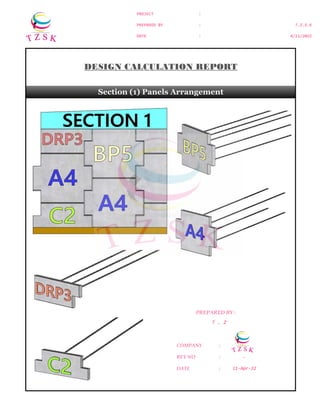
1. PROJECT :
PREPARED BY :
DATE :
T.Z.S.K
4/11/2022
T . Z
COMPANY :
REV NO : -
DATE :
DESIGN CALCULATION REPORT
Section (1) Panels Arrangement
PREPARED BY :
11-Apr-22
2. PROJECT :
PREPARED BY :
DATE :
T.Z.S.K
4/11/2022
Design Calculation Results (SECTION 1)
SUMMARY
EXTERNAL STABILITY
Sliding
Case I F.S = 3.17 > 1.50 OK
Case II F.S = 3.82 > 1.50 OK
Case III F.S = 4.24 > 1.50 OK
Case IV F.S = 3.01 > 1.50 OK
Case V F.S = 3.82 > 1.50 OK
Overturning
Case I F.S = 7.01 > 2.00 OK
Case II F.S = 7.53 > 2.00 OK
Case III F.S = 8.48 > 2.00 OK
Case IV F.S = 3.82 > 2.00 OK
Case V F.S = 7.53 > 2.00 OK
Bearing Capacity
Case I q = 110.71 kN/m2
Case II q = 173.98 kN/m2
Control
Case III q = 118.19 kN/m2
Case IV q = 128.60 kN/m2
Case V q = 173.98 kN/m2
INTERNAL STABILITY
Pullout Resistance
Layer 1 Tmax = 9.77 kN per strip < 16.20 kN OK
Layer 2 Tmax = 13.05 kN per strip < 21.75 kN OK
Layer 3 Tmax = 16.77 kN per strip < 28.28 kN OK
Layer 4 Tmax = 18.73 kN per strip < 33.97 kN OK
Tensile Resistance
Layer 1 Tmax = 18.82 kN per strip < 33.51 kN OK
Layer 2 Tmax = 22.99 kN per strip < 33.51 kN OK
Layer 3 Tmax = 26.68 kN per strip < 33.51 kN OK
Layer 4 Tmax = 30.20 kN per strip < 33.51 kN OK
Pullout Resistance
Layer 1 Tmax = 14.56 kN per strip < 18.00 kN OK
Layer 2 Tmax = 18.17 kN per strip < 24.17 kN OK
Layer 3 Tmax = 22.58 kN per strip < 31.42 kN OK
Layer 4 Tmax = 25.22 kN per strip < 37.74 kN OK
Tensile Resistance
Layer 1 Tmax = 23.61 kN per strip < 44.67 kN OK
Layer 2 Tmax = 28.11 kN per strip < 44.67 kN OK
Layer 3 Tmax = 32.49 kN per strip < 44.67 kN OK
Layer 4 Tmax = 36.70 kN per strip < 44.67 kN OK
Pullout Resistance
Layer 1 Tmax = 12.13 kN per strip < 18.00 kN OK
Layer 2 Tmax = 16.59 kN per strip < 24.17 kN OK
Layer 3 Tmax = 20.31 kN per strip < 31.42 kN OK
Layer 4 Tmax = 22.27 kN per strip < 37.74 kN OK
Tensile Resistance
Layer 1 Tmax = 22.97 kN per strip < 44.67 kN OK
Layer 2 Tmax = 29.21 kN per strip < 44.67 kN OK
Layer 3 Tmax = 32.90 kN per strip < 44.67 kN OK
Layer 4 Tmax = 36.42 kN per strip < 44.67 kN OK
Seismic
Impact
Seismic
Impact
Static
Seismic
Impact
Static
Static
Seismic
Impact
Static
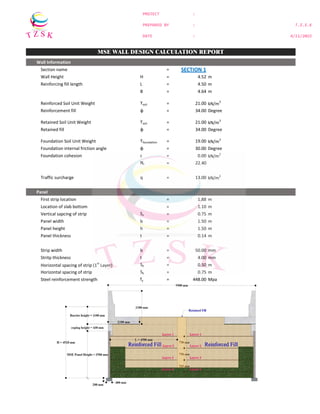
3. PROJECT :
PREPARED BY :
DATE :
T.Z.S.K
4/11/2022
Wall Information
Section name = SECTION 1
Wall Height H = 4.52 m
Reinforcing fill length L = 4.50 m
B = 4.64 m
Reinforced Soil Unit Weight Ï’soil = 21.00 kN/m3
Reinforcement fill φ = 34.00 Degree
Retained Soil Unit Weight Ï’soil = 21.00 kN/m3
Retained fill φ = 34.00 Degree
Foundation Soil Unit Weight Ï’foundation = 19.00 kN/m3
Foundation internal friction angle φ = 30.00 Degree
Foundation cohesion c = 0.00 kN/m2
Nr = 22.40
Traffic surcharge q = 13.00 kN/m2
Panel
First strip location = 1.88 m
Location of slab bottom = 1.10 m
Vertical sapcing of strip Sv = 0.75 m
Panel width b = 1.50 m
Panel height h = 1.50 m
Panel thickness t = 0.14 m
Strip width b = 50.00 mm
Stritp thickness t = 4.00 mm
Horizontal spacing of strip (1st
Layer) Sh = 0.50 m
Horizontal spacing of strip Sh = 0.75 m
Steel reinforcement strength fy = 448.00 Mpa
Load Factor, Ï’ (LRFD 11.5.5)
Typical application
Bearing Resistance
Vertical Ï’EV = 1.35
Horizontal Ï’EH = 1.5
Sliding and Eccentricity
Vertical Ï’EV = 1
Horizontal Ï’EH = 1.5
Live Load Surcharge on MSE Wall
Bearing and reinforcement tensile Resistance Ï’LS = 1.75
Sliding, eccentricity and reinforcement pullout resistance
Ï’LS = 1.75
Resistance Factor, φ (LRFD Table 11.5.6-1)
Mechanically Stabilized Earth Walls
Pullout resistance of tensile reinforcement
Static loading = 0.9
MSE WALL DESIGN CALCULATION REPORT
4. PROJECT :
PREPARED BY :
DATE :
T.Z.S.K
4/11/2022
Load Cases
Vertical
Load
Horizontal
Load
Live
Load
Load Factor Ï’ (LRFD 11.5.5) Ï’EV Ï’EH Ï’LS
Case I Strength I 1.00 1.50 -
Case II Strength II 1.35 1.50 1.75
Case III Service I 1.00 1.00 1.00
Resistance Factor φP φT
Case IV Static loading 0.90 0.75
Case V Combined static and impact loading 1.00 1.00
I. External Stability
Static Mass Stability
Vertical loads
Reinforced Soil
V1 = Ï’soil H L
= 21.00 x 4.52 x 4.50
= 427.14 kN/m
Case I V1 = 427.14 x 1
V1 = 427.14 kN/m
Case II V1 = 427.14 x 1.35
V1 = 576.64 kN/m
Case III V1 = 427.14 x 1
V1 = 427.14 kN/m
Forces acting on the MSE Wall
Forces :
V1 = Ï’soil H L
V2 = qs L
F1 = 0.5 Ï’ H2 Ka
F2 = qs H Kaf
5. PROJECT :
PREPARED BY :
DATE :
T.Z.S.K
4/11/2022
Moment arm of V1 = 2.25 m
MV1 = 427.14 x 2.25
MV1 = 961.065 kN-m/m
Case I MV1 = 961.065 KN-m/m
Case II MV1 = 1297.44 KN-m/m
Case III MV1 = 961.07 KN-m/m
Traffic surcharge
V2 = q L
V2 = 13.00 x 4.5
V2 = 58.50 kN/m
Factored V2 = 58.50 x 1.75
Factored V2 = 102.38 kN/m
Moment arm of V2 = 2.25 m
MV2 = 58.50 x 2.25
MV2 = 131.63 kN-m/m
Factored MV2 = 102.38 x 2.25
Factored MV2 = 230.34 kN-m/m
Case I ∑V = 427.14 kN/m
Case II ∑V = 679.01 kN/m
Case III ∑V = 485.64 kN/m
Case I ∑Mv = 961.07 kN-m/m
Case II ∑Mv = 1527.78 kN-m/m
Case III ∑Mv = 1092.69 kN-m/m
Horizontal loads
ka = tan(45 - φ/2)2
For retained ka = 0.28
For surcharge kaf = 0.28
Retained Soil
F1 = 0.5 Ï’soil H2
Ka
= 60.65 kN/m
Case I F1 = 90.97 kN/m
Case II F1 = 90.97 kN/m
Case III F1 = 60.65 kN/m
Moment arm of F1 = 1.51 m
Case I MF1 = 137.07 kN-m/m
Case II MF1 = 137.07 kN-m/m
Case III MF1 = 91.38 kN-m/m
6. PROJECT :
PREPARED BY :
DATE :
T.Z.S.K
4/11/2022
Traffic surcharge
F2 = q H Kaf
F2 = 16.61 kN/m
Factored F2 = 29.07 kN/m
Moment arm of F2 = 2.26 m
MF2 = 37.54 kN-m/m
Factored MF2 = 65.70 kN-m/m
Case I ∑F = 90.97 kN/m
Case II ∑F = 120.04 kN/m
Case III ∑F = 77.26 kN/m
Case I ∑MF = 137.07 kN-m/m
Case II ∑MF = 202.77 kN-m/m
Case III ∑MF = 128.92 kN-m/m
Sliding (LRFD 11.10.5.3)
Sliding F.S = ∑V x tanφ
∑F
Case I F.S = 3.17 > 1.5 OK
Case II F.S = 3.82 > 1.5 OK
Case III F.S = 4.24 > 1.5 OK
Overturning (LRFD 11.10.5.3)
Overturning F.S = ∑Mv
∑MF
Case I = 7.01 ≥ 2 OK
Case II = 7.53 ≥ 2 OK
Case III = 8.48 ≥ 2 OK
Bearing Capacity at Base
Eccentricity e = L - ∑Mv-∑Mf
2 ∑V
Case I e = 0.32 m ≤ 0.77 m OK
Case II e = 0.30 m ≤ 0.75 m OK
Case III e = 0.27 m ≤ 0.75 m OK
7. PROJECT :
PREPARED BY :
DATE :
T.Z.S.K
4/11/2022
σv = ∑V
L-2e
Case I σv = 110.71 kN/m2
Case II σv = 173.98 kN/m2
Case III σv = 118.19 kN/m2
11.4.2 (f) qult = cf Nc + 0.5 (L-2e) Ï’f Nr
qult = 844.62 kN/m2
F.S = qult
σv
= 7.63 > 1.5 OK
Sliding at base of first grid
F1 at first grid F1 = 0.5 Ï’b d2
Ka
= 50.12 kN/m
F2 = q d ka
= 15.88 kN/m
∑F = 66.00 kN/m
F.S = ϒb d L tanφ C
∑F
= 4.17 > 1.5 OK
8. PROJECT :
PREPARED BY :
DATE :
T.Z.S.K
4/11/2022
II. Internal Stability
Distance from Top Steel Strip Tributary Spacing
d1 = 1.88 m V1 = 1.18 m
d2 = 2.63 m V2 = 0.75 m
d3 = 3.38 m V3 = 0.75 m
d4 = 4.13 m V4 = 0.77 m
Force developed in the reinforcement
Static Load
Compute Kr (LRFD Figure 11.10.6.2.1-3)
At Z = 0 Kr = 0.48
Under Z = 6 m Kr = 0.34
MSE Wall Panel Arrangement for Section 1
LRFD 11.4.3.Fig 29
Variation of stress ratio with depth in MSE Wall
Friction
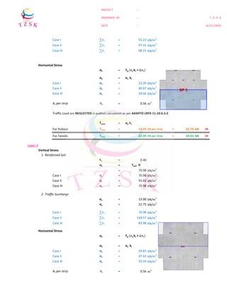
9. PROJECT :
PREPARED BY :
DATE :
T.Z.S.K
4/11/2022
Layer 1
Vertical Stress
1 Reinforced Soil
Kr = 0.44
σv = ϒsoil H
= 39.48 kN/m2
Case I σv = 39.48 kN/m2
Case II σv = 53.30 kN/m2
Case III σv = 39.48 kN/m2
=
2 Traffic Surcharge
σv = 13.00 kN/m2
σv = 22.75 kN/m2
Case I ∑σv = 39.48 kN/m2
Case II ∑σv = 76.05 kN/m2
Case III ∑σv = 52.48 kN/m2
Horizontal Stress
σh = ϒp (σv kr + Δσh)
σh = σv kr
Case I σh = 26.06 kN/m2
Case II σh = 50.19 kN/m2
Case III σh = 23.09 kN/m2
At per strip At = 0.38 m2
Traffic Load are NEGLECTED in pullout calculation as per AASHTO LRFD 11.10.6.3.2.
Tmax = σh Sv
For Pullout Tmax = 9.77 kN per strip < 16.20 kN OK
For Tensile Tmax = 18.82 kN per strip < 33.51 kN OK
Layer 2
Vertical Stress
1 Reinforced Soil
Kr = 0.42
σv = ϒsoil H
= 55.23 kN/m2
Case I σv = 55.23 kN/m2
Case II σv = 74.56 kN/m2
Case III σv = 55.23 kN/m2
2 Traffic Surcharge
σv = 13.00 kN/m2
σv = 22.75 kN/m2
BP 5
10. PROJECT :
PREPARED BY :
DATE :
T.Z.S.K
4/11/2022
Case I ∑σv = 55.23 kN/m2
Case II ∑σv = 97.31 kN/m2
Case III ∑σv = 68.23 kN/m2
Horizontal Stress
σh = ϒp (σv kr + Δσh)
σh = σv kr
Case I σh = 23.20 kN/m2
Case II σh = 40.87 kN/m2
Case III σh = 28.66 kN/m2
At per strip At = 0.56 m2
Traffic Load are NEGLECTED in pullout calculation as per AASHTO LRFD 11.10.6.3.2.
Tmax = σh Sv
For Pullout Tmax = 13.05 kN per strip < 21.75 kN OK
For Tensile Tmax = 22.99 kN per strip < 33.51 kN OK
Layer 3
Vertical Stress
1 Reinforced Soil
Kr = 0.40
σv = ϒsoil H
= 70.98 kN/m2
Case I σv = 70.98 kN/m2
Case II σv = 95.82 kN/m2
Case III σv = 70.98 kN/m2
2 Traffic Surcharge
σv = 13.00 kN/m2
σv = 22.75 kN/m2
Case I ∑σv = 70.98 kN/m2
Case II ∑σv = 118.57 kN/m2
Case III ∑σv = 83.98 kN/m2
Horizontal Stress
σh = ϒp (σv kr + Δσh)
σh = σv kr
Case I σh = 29.81 kN/m2
Case II σh = 47.43 kN/m2
Case III σh = 33.59 kN/m2
At per strip At = 0.56 m2
BP 5
11. PROJECT :
PREPARED BY :
DATE :
T.Z.S.K
4/11/2022
Traffic Load are NEGLECTED in pullout calculation as per AASHTO LRFD 11.10.6.3.2.
Tmax = σh Sv
For Pullout Tmax = 16.77 kN per strip < 28.28 kN OK
For Tensile Tmax = 26.68 kN per strip < 33.51 kN OK
Layer 4
Vertical Stress
1 Reinforced Soil
Kr = 0.38
σv = ϒsoil H
= 86.73 kN/m2
Case I = 86.73 kN/m2
Case II = 117.09 kN/m2
Case III = 86.73 kN/m2
2 Traffic Surcharge
σv = 13.00 kN/m2
σv = 22.75 kN/m2
Case I ∑σv = 86.73 kN/m2
Case II ∑σv = 139.84 kN/m2
Case III ∑σv = 99.73 kN/m2
Horizontal Stress
σh = ϒp (σv kr + Δσh)
σh = σv kr
Case I σh = 33.30 kN/m2
Case II σh = 53.70 kN/m2
Case III σh = 38.30 kN/m2
At per strip At = 0.56 m2
Traffic Load are NEGLECTED in pullout calculation as per AASHTO LRFD 11.10.6.3.2.
Tmax = σh Sv
For Pullout Tmax = 18.73 kN per strip < 33.97 kN OK
For Tensile Tmax = 30.20 kN per strip < 33.51 kN OK
12. PROJECT :
PREPARED BY :
DATE :
T.Z.S.K
4/11/2022
Resistance in friction of one strip against soil (LRFD Equation 11.10.6.3.2-1)
At Z = 0 F*
= 1.80
Under Z = 6 m F*
= 0.67
LRFD Figure 11.10.6.3.2-1
Default Values for the Pullout Friction Factor, F*
α = 1
C = 2.00 for strip
Rc = 0.10 For 3 strip per panel
Rc = 0.07 For 2 strip per panel
Pullout calculation at each reinforcement level
Le ≥ Tmax ≥ 1 m
φ F* α σv C Rc
Layer 1
F*
= 1.45
Le = 1.83 m ≥ 1 m
Take Le = 1.83 m
Layer 2
F*
= 1.3
Le = 2.67 m ≥ 1 m
Take Le = 2.67 m
Layer 3
F*
= 1.16
Le = 2.70 m ≥ 1 m
Take Le = 2.70 m
Layer 4
F*
= 1.02
Le = 2.85 m ≥ 1 m
Take Le = 2.85 m
13. PROJECT :
PREPARED BY :
DATE :
T.Z.S.K
4/11/2022
Calculate L A at each layer
for H/2 from bottom LA = 0.6 (H1 - d) for inextensible reinforcement
for H/2 from top LA = 0.3 H1 for inextensible reinforcement
LA1 = 1.36 m
LA2 = 1.13 m
LA3 = 0.68 m
LA4 = 0.23 m
LRFD Figure 11.10.6.3.1-1
Location of Potential Failure Surface for Internal Stability Design of MSE Walls
Calculate L T at each layer
Layer 1 LT1 = 3.18 m < 4.50 m OK
Layer 2 LT2 = 3.80 m < 4.50 m OK
Layer 3 LT3 = 3.38 m < 4.50 m OK
Layer 4 LT4 = 3.08 m < 4.50 m OK
Allowable Tensile Strength
Design Life = 100 years
For Corrosion Losses Ec = En - Es
Loss of galvanizing = 0.015 mm/yr for first 2 year
= 0.004 mm/yr for subsequent years
Zinc coating lift = 16.00 years
Loss of carbon steel = 0.012 mm/yr after zinc depletion
Ec = 1.99 mm
Ac = 99.72 mm2
14. PROJECT :
PREPARED BY :
DATE :
T.Z.S.K
4/11/2022
Tal = AC FY
Case V φTall = 44.67 kN
Case IV φTall = 33.51 kN
Pullout Resistance Strength
C11.10.6.3.2 P = F*
α σv Le C b
Layer 1 Case V φP = 18.00 kN
Case IV φP = 16.20 kN
Layer 2 Case V φP = 24.17 kN
Case IV φP = 21.75 kN
Layer 3 Case V φP = 31.42 kN
Case IV φP = 28.28 kN
Layer 4 Case V φP = 37.74 kN
Case IV φP = 33.97 kN
Connection Strength
Strip width b = 60 mm
Stritp thickness t = 4 mm
Yield Strength Fy = 345 Mpa
C11.10.6.3.2 Tac = AC FY
Case V φTac = 63.48 kN > 44.67 kN OK
Case IV φTac = 47.61 kN > 33.51 kN OK
III. External Stability with Seismic
Peak Ground Acceleration a0/g = 0.46
11.6.5.2.1 Horizontal acceleration coefficient
kh = 0.5 Kho
= 0.23
ζ = Arc tan(Kh)
= 12.95
kae = cos2
(φ - ζ)
cos ( ζ ) cos (ζ + δ) (1 + √(sin(φ + δ) sin(φ - ζ - δ)/cos (ζ + δ) cosδ))2
kae = 0.871
0.950 x 2.114
= 0.434
11.6.5.3-2 Horizontal Seismic Thrust PAE = 0.5 KAE Ï’ H2
= 93.06 kN/m
15. PROJECT :
PREPARED BY :
DATE :
T.Z.S.K
4/11/2022
Moment arm of PAE = 1.51 m
Moment MAE = 140.22 KN-m
Horizontal Inertia Force PIR = 0.5 Kh Ï’ H2
= 49.34 kN/m
Moment arm of PIR = 2.26 m
Moment MIR = 111.51 KN-m
∑MF = 251.72 KN-m
Sliding (LRFD 11.10.5.3)
Sliding F.S = ∑V x tanφ
∑F
Rv = 427.14 kN/m
Moment arm of Pv = 2.25 m
Moment Mv = 961.07 KN-m
Rh = 95.87 kN/m
F.S = 3.01 > 1.5 OK
Overturning (LRFD 11.10.5.3)
Overturning F.S = ∑Mv
∑MF
= 3.82 > 2 OK
Bearing Capacity at Base
Eccentricity e = L - ∑Mv-∑Mf
2 ∑V
= 0.59 < 0.75 OK
σv = ∑V
L - 2e
σv = 128.60 kN/m2
16. PROJECT :
PREPARED BY :
DATE :
T.Z.S.K
4/11/2022
qult = cf Nc + 0.5 (L-2e) Ï’f Nr
qult = 706.78 kN/m2
F.S = qult
σv
= 5.50 > 1.5 OK
IV. Internal Stability with Seismic
PI = Kh Wa
= 22.20 kN/m
Tmd = Pi Lei / ∑Lei
Layer 1 Tmd = 4.78 kN per strip
Layer 2 Tmd = 5.12 kN per strip
Layer 3 Tmd = 5.81 kN per strip
Layer 4 Tmd = 6.49 kN per strip
Ttotal = Tmax + Tmd
Layer 1 For Pullout Ttotal = 14.56 kN per strip < 18.00 kN OK
For Tensile Ttotal = 23.61 kN per strip < 44.67 kN OK
Layer 2 For Pullout Ttotal = 18.17 kN per strip < 24.17 kN OK
For Tensile Ttotal = 28.11 kN per strip < 44.67 kN OK
Layer 3 For Pullout Ttotal = 22.58 kN per strip < 31.42 kN OK
For Tensile Ttotal = 32.49 kN per strip < 44.67 kN OK
Layer 4 For Pullout Ttotal = 25.22 kN per strip < 37.74 kN OK
For Tensile Ttotal = 36.70 kN per strip < 44.67 kN OK
17. PROJECT :
PREPARED BY :
DATE :
T.Z.S.K
4/11/2022
V. Impact Load
Width of slab b = 2.1 m
Depth of slab h = 1.1 m
Eccetricity of traffic barrier e = 0.12 m
Slab Length L = 6 m
11.10.10.2 Static impact Load P = 44.48 kN
Earth pressure F1 = 0.5 Ka Ï’ h2
Case I F1 = 3.59 kN/m
Case II F1 = 4.85 kN/m
Traffic surcharge F2 = Ka q h
Case I F2 = 4.04 kN/m
Case II F2 = 7.08 kN/m
PH1 = 7.41 kN/m
Case I ∑ F 11.01 kN/m
Case II ∑ F = 19.34 kN/m
Horizontal pressure due to traffic barrier
L1 = (cr + bf - 2e') (tan 45 + φ/2)
= 3.50 m
Δσhmax = 2 ∑F / L1
Case I Δσhmax = 6.29 kN/m2
Case II Δσhmax = 11.06 kN/m2
18. PROJECT :
PREPARED BY :
DATE :
T.Z.S.K
4/11/2022
Tmax = σh Sv
Layer 1
For Pullout Tmax = 12.13 kN per strip < 18.00 kN OK
For Tensile Tmax = 22.97 kN per strip < 44.67 kN OK
Layer 2
For Pullout Tmax = 16.59 kN per strip < 24.17 kN OK
For Tensile Tmax = 29.21 kN per strip < 44.67 kN OK
Layer 3
For Pullout Tmax = 20.31 kN per strip < 31.42 kN OK
For Tensile Tmax = 32.90 kN per strip < 44.67 kN OK
Layer 4
For Pullout Tmax = 22.27 kN per strip < 37.74 kN OK
For Tensile Tmax = 36.42 kN per strip < 44.67 kN OK