Mvhr installation guide_final_11_02_11
ŌĆó
0 likesŌĆó266 views

This document provides an installation guide and checklist for mechanical ventilation with heat recovery (MVHR) systems. It contains guidance on best practices for ductwork installation, unit fixing, electrical connection, system balancing and calibration, and customer handover. Installers are advised to complete the checklist for each installation to ensure proper installation and to provide performance data for the SAP assessment procedure. The checklist contains questions on topics like ductwork design, insulation, air tightness, unit mounting, electrical connection, air flow balancing, and customer instructions.


Mvhr installation guide_final_11_02_11
- 1. Standard Assessment Procedure 2005 ŌĆō Appendix Q MVHR Installation Guide Installation Guide and Checklist Mechanical Ventilation with Heat Recovery (Version ŌĆō 11 February 2011) The Electric Heating and Ventilation Association have developed this guidance and checklist document in partnership with the Residential Ventilation Association (a HEVAC association), BRE and EST. NOTE: This guide and checklist has been superseded for dwellings assessed under ŌĆśThe Building Regulations 2010ŌĆÖ, specifically SAP 2009 and Approved Documents L and F. Completion of this document is therefore only required for dwellings assessed by SAP 2005. Customer Details Customer Name: Address: Telephone Number: Date of Installation: Name of Lead Contractor: Design Project Number: It should be noted that this guidance is not intended to replace product manufacturer installation instructions; it is a generic addition which defines good practice. Installers are advised to complete this form for each installation and keep a copy to provide to Building Control Officers in case requested.
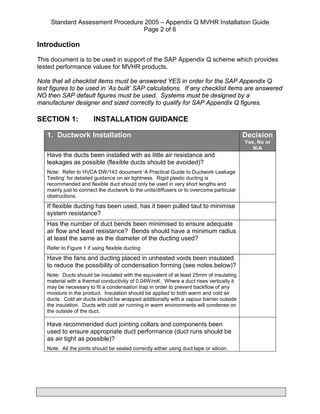
- 2. Standard Assessment Procedure 2005 ŌĆō Appendix Q MVHR Installation Guide Page 2 of 6 Introduction This document is to be used in support of the SAP Appendix Q scheme which provides tested performance values for MVHR products. Note that all checklist items must be answered YES in order for the SAP Appendix Q test figures to be used in ŌĆśAs builtŌĆÖ SAP calculations. If any checklist items are answered NO then SAP default figures must be used. Systems must be designed by a manufacturer designer and sized correctly to qualify for SAP Appendix Q figures. SECTION 1: INSTALLATION GUIDANCE 1. Ductwork Installation Decision Yes, No or N/A Have the ducts been installed with as little air resistance and leakages as possible (flexible ducts should be avoided)? Note: Refer to HVCA DW/143 document ŌĆśA Practical Guide to Ductwork Leakage TestingŌĆÖ for detailed guidance on air tightness. Rigid plastic ducting is recommended and flexible duct should only be used in very short lengths and mainly just to connect the ductwork to the units/diffusers or to overcome particular obstructions. If flexible ducting has been used, has it been pulled taut to minimise system resistance? Has the number of duct bends been minimised to ensure adequate air flow and least resistance? Bends should have a minimum radius at least the same as the diameter of the ducting used? Refer to Figure 1 if using flexible ducting Have the fans and ducting placed in unheated voids been insulated to reduce the possibility of condensation forming (see notes below)? Note: Ducts should be insulated with the equivalent of at least 25mm of insulating material with a thermal conductivity of 0.04W/mK. Where a duct rises vertically it may be necessary to fit a condensation trap in order to prevent backflow of any moisture in the product. Insulation should be applied to both warm and cold air ducts. Cold air ducts should be wrapped additionally with a vapour barrier outside the insulation. Ducts with cold air running in warm environments will condense on the outside of the duct. Have recommended duct jointing collars and components been used to ensure appropriate duct performance (duct runs should be as air tight as possible)? Note: All the joints should be sealed correctly either using duct tape or silicon.
- 3. Standard Assessment Procedure 2005 ŌĆō Appendix Q MVHR Installation Guide Page 3 of 6 Figure 1 Ductwork Visual Guide Source: Approved Document F (England & Wales) 2006 2. Unit Fixing Decision Yes, No or N/A Has the heat recovery unit been effectively insulated? Note: If the unit is not pre-insulated then ensure additional insulation is installed around the unit to minimise heat loss Has the heat recovery unit been fixed to a stable element of the building fabric (e.g. wall or floor) using manufacturer recommended/supplied fixing brackets? Has the condensation drain been fitted and the pipe insulated? Have approved acoustic/anti-vibration mountings been used? Note: Special attention is needed to avoid transmission and stress to duct joints Has the unit been installed in a position that will permit access for maintenance purposes? Have all grilles or ductwork that penetrate the buildingŌĆÖs air barrier, as identified in the construction drawings, been sealed to ensure continuity of the air barrier?
- 4. Standard Assessment Procedure 2005 ŌĆō Appendix Q MVHR Installation Guide Page 4 of 6 Figure 2 Sample Mounting Positions 3. Electrical Connection Decision Yes, No or N/A Has the rating label been verified to establish suitability for the installation strategy and whether an earth is required (e.g. voltage, class I or II product status)? Has a local isolator been provided to enable the unit to be isolated for maintenance purposes? Has the unit been fused in accordance with its power rating? SECTION 2: COMMISSIONING GUIDANCE
- 5. Standard Assessment Procedure 2005 ŌĆō Appendix Q MVHR Installation Guide Page 5 of 6 1. System Balancing & Calibration Decision Yes, No or N/A Has the air flow been checked using a proprietary device such as an anemometer (recommended)? Have the controls been set following a defined process? Refer to figure 3 flow diagram Have all distribution grilles been locked where possible to minimise unapproved occupant adjustment? Figure 3 Ensure all external and internal windows and doors are closed Set fan speed using manufacturer data table Set normal daytime air flow on extract points starting at location furthest from unit Set normal daytime air flow on input points starting at location furthest from unit Step 1 Step 2 Step 3 Step 4 Step 5 Set fan speed to boost and measure extract rates at each location, adjust fan speed setting as required to achieve required flow
- 6. Standard Assessment Procedure 2005 ŌĆō Appendix Q MVHR Installation Guide Page 6 of 6 2. Handover and Control/Maintenance Advice Decision Yes, No or N/A Has the customer been supplied with suitable documentation detailing maintenance and operational requirements? Has the customer been advised that opening windows is not recommended during normal use in order to ensure the energy efficient operation and performance of the balanced system? Has the customer been advised not to seal natural air flows from room to room (e.g. avoid door seals and thick pile carpets) Has the customer been advised not to alter settings post- commissioning? Has the customer been advised to clean the filters as explained in the manufacturerŌĆÖs instructions?