MX Lap Timer - An automatic stopwatch for Motocross
•
1 like•590 views

This document describes an automatic stopwatch system for motocross using infrared transmission. The system has two main modules: a transmitter module that generates infrared pulses and a main module that calculates lap times, displays data on an LCD, and stores lap times in an SD card. The main module uses an infrared receiver to detect pulses from the transmitter and calculates lap times and performance metrics. Validation testing with an oscilloscope confirmed the system accurately detects transmitted pulses and measures lap times. The stored lap time data can be analyzed with graphs to evaluate a rider's performance over a season.


MX Lap Timer - An automatic stopwatch for Motocross
- 1. MX Lap Timer An automatic stopwatch for Motocross Guilherme Pohl Applied Electronics Professor Walter Gontijo December 9, 2014
- 2. Objective â—Ź Develop an automatic stopwatch using an Infrared (IR) transmitter and receiver to be used in Motocross â—Ź Create an easy way to analyze your seasons 2
- 3. Functionalities â—Ź Calculate and display the current lap time â—Ź Calculate the time difference between the current lap and the previous lap â—Ź Display the best lap â—Ź Software brighlight adjust â—Ź Store the lap times in a .csv file â—Ź Plot a lap time x lap graph in Excel 3
- 4. Project Overview This project can be divided into two modules: â—Ź Transmitter module: Responsible for generating the pulse sequence â—Ź Main Module: Responsible for calculate the lap time, the difference between the previous lap, display the data on the LCD Display and store the lap time into the SD Card 4
- 5. Transmitter Design 5 Block Diagram of the Transmitter Module
- 6. Infrared (IR) Code 6 IR Code used in the MX Lap Timer
- 8. Transmitter PCB Layout 8 Transmitter PCB Layout
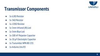
- 9. Transmissor Components ● 1x 6.8Ω Resistor ● 1x 1kΩ Resistor ● 1x 220Ω Resistor ● 1x 5mm Infrared (IR) Led ● 1x 5mm Blue Led ● 1x 100 nF Polyester Capacitor ● 1x 10 µF Electrolytic Capacitor ● 1x Transmitter NPN BD 233 ● 1x Arduino Uno R3 9
- 10. Main Module Design 10 Main Module Block Diagram
- 11. Main Module PCB Layout 11
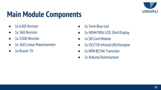
- 13. Main Module Components ● 1x 6.8Ω Resistor ● 1x 1kΩ Resistor ● 1x 220Ω Resistor ● 1x 1kΩ Linear Potentiometer ● 1x Buzzer 5V 13 ● 1x 5mm Blue Led ● 1x HD44780U LCD 20x4 Display ● 1x SD Card Module ● 1x VS1738 Infrared (IR) Receptor ● 1x NPN BC546 Transistor ● 1x Arduino Duemilanove
- 14. Infrared (IR) Receptor 14 Block Diagram of the VS1738 Infrared(IR) Receptor
- 16. Infrared (IR) Receptor 16 Infrared(IR) Receptor Input Infrared(IR) Transmitter Output Stop the transmission required by the receptor to confirm the code’s receipt Repeat
- 17. LCD 20x4 Display The display has a parallel interface, this means the Arduino needs to control many pins of the display at the same time in order to display the messages. 17 Pins Utilized Connection VSS GND VDD +5V VE Potentiometer Signal Pin Register Select (RS) D9 Read/Write (RD/WR) GND Enable (E) D8 D4,D5,D6,D7 D7, D6, D5, D4 Backlight Anode +5v Backlight Cathode Collector of BC546
- 18. SD Card Module This module communicate with the microcontroller using a serial peripheral interface bus (SPI), that is a synchronous protocol used by the Arduino to communicate with other peripherals and microcontrollers. 18 SD Card’s Pin Arduino’s Pin CS D10 SCK D13 MOSI D11 MISO D12
- 20. System Validation The validation of the system was made analyzing the output of the IR Transmissor and the input of IR Receptor signal pin utilizing an oscilloscope. 20
- 21. System Validation 21 Zoom-in of one valid pulse
- 22. System Validation 22 Zoom-in of the the Transmitter Output and the Receiver Input
- 23. System Validation 23 Delay of the Receiver Input signal
- 24. Computational Analysis Analyzing the graph generated with the data acquired in one season is possible to verify the rider's performance for each lap. 24