Nozzles - Lecture A
- 1. Thermodynamics ÔÇô 2 Fall Semester, 2014-2015 Lecture ÔÇô A Nozzles Dr. Ahmed Rezk 1
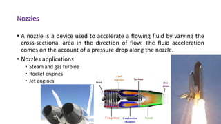
- 2. Nozzles ÔÇó A nozzle is a device used to accelerate a flowing fluid by varying the cross-sectional area in the direction of flow. The fluid acceleration comes on the account of a pressure drop along the nozzle. ÔÇó Nozzles applications ÔÇó Steam and gas turbine ÔÇó Rocket engines ÔÇó Jet engines 2
- 3. Governing equations ÔÇó Steady flow continuity equation ÔÇó Where m is the mass flow rate at inlet section (in), outlet section (out) and any section (x) along nozzle passage. The mass flow rate can be determined as: 3 Constant´Ç¢m´Çª xoutin mmm ´Çª´Çª´Çª ´Ç¢´Ç¢ m´Çª
- 4. Governing equations ÔÇó ¤ü is the flowing fluid density (kg/m3) ÔÇó V is the velocity normal to the flow area (m/s) ÔÇó A the cross-sectional area (m2) ÔÇó ã▓ fluid specific volume (m3/kg) 4 ´Ç¿ ´Ç®skg v AV AVm /´Ç¢´Ç¢ ´ü▓´Çª x xx out outout in inin v VA v VA v VA ´Ç¢´Ç¢
- 5. Governing equations ÔÇó Steady flow energy equation (per unit mass) ÔÇó Apply the following assumption: ÔÇó Negligible heat losses (adiabatic). ÔÇó No work done on or by the system. ÔÇó The nozzle passage is very small and hence the change in the potential energy is negligible even in vertical nozzle. 5 ´Ç¿ ´Ç® ´Ç¿ ´Ç®inout inout inout zzg VV hhwq ´Ç¡´âù´Ç½´âÀ ´âÀ ´â© ´â ´âº ´âº ´â¿ ´âª ´Ç¡ ´Ç½´Ç¡´Ç¢´Ç¡ 2 22
- 6. Governing equations ÔÇó The steady flow energy equation can be describe as: ÔÇó Applying the steady flow energy equation between section 1 and any section X along the fluid flow along the nozzle passage. 6 outin inout hh VV ´Ç¡´Ç¢ ´Ç¡ 2 22 ´Ç¿ ´Ç®XX hhVV ´Ç¡´âù´Ç½´Ç¢ 1 2 1 2 2 ´Ç¿ ´Ç®XX hhVV ´Ç¡´âù´Ç½´Ç¢ 1 2 1 2
- 7. Nozzle shape ÔÇó This part is to find the change in the nozzle cross-sectional area to increase the fluid flow velocity to the required value. ÔÇó Consider a stream of fluid flow of inlet pressure and enthalpy of Pin and hin. Assume the inlet velocity (Vin) is very small. Now describe the change of the nozzle area to increase the fluid velocity. ÔÇó Apply the steady state momentum equation and replace the velocity with the corresponding term from energy equation, and hence: 7
- 8. Nozzle shape ÔÇó The relation between the initial and final thermo-physical properties depends on the thermodynamic process. ÔÇó Assume frictionless fluid flow + adiabatic flow = reversible adiabatic (isentropic) process. ÔÇó At any section X, sx=s1=constant. 8 ´Ç¿ ´Ç®X XX hhV v m A ´Ç¡´âù´Ç½ ´Ç¢ 1 2 1 2´Çª X XX v VA m ´Ç¢´Çª X XX V v m A ´Ç¢ ´Çª
- 9. Nozzle shape ÔÇó At any section, by knowing the pressure and constant entropy, other parameters can be determined. 9
- 10. Nozzle shape ÔÇó The following graph presents the effect of reducing gas pressure and the influence on the cross-sectional area and flow velocity. 10 ÔÇó It is observed that the area decreases initially, hit the minimum at certain point then increases again. ÔÇó The area decreases, when v-j increases less rapidly than V-jj. ÔÇó The area increases, when v-jj increases more rapidly than V-j. X XX V v m A ´Ç¢ ´Çª
- 11. Nozzle shape (case study) 11 020406080100 FlowPressure (kPa) Area Velocity
- 12. Nozzle shape ÔÇó Based on the aforementioned information. That type of nozzle is called a convergent-divergent nozzle (the following graph). 12
- 13. Nozzle shape ÔÇó The section of minimum area is called the throat of the nozzle. ÔÇó The velocity at the throat of a nozzle operating at its designed pressure ratio is the velocity of sound at the throat conditions. ÔÇó The flow up to the throat is sub-sonic; the flow after the throat is supersonic 13 ÔÇó The specific volume of a liquid is constant over a wide pressure range, and therefore nozzles for liquids are always convergent.
- 14. Nozzle critical pressure ratio ÔÇó You can design a convergent divergent nozzle where the velocity at the nozzle through equal the sound velocity. ÔÇó The ratio of the pressure at the section of sonic velocity to the pressure at nozzle inlet is called the critical pressure ratio Z c. ÔÇó Solve the energy and momentum equations between the inlet section and any point along the nozzle passage. ÔÇó In most practical applications the inlet velocity is negligible, so the energy equation can be reduced to. 14 ´Ç¿ ´Ç®hhV ´Ç¡´âù´Ç¢ 12´Ç¿ ´Ç®hhVV ´Ç¡´âù´Ç½´Ç¢ 1 2 1 2
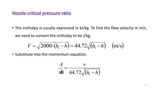
- 15. Nozzle critical pressure ratio ÔÇó The enthalpy is usually expressed in kJ/kg. To find the flow velocity in m/s, we need to convert the enthalpy to be J/kg. ÔÇó Substitute into the momentum equation. 15 ´Ç¿ ´Ç® ´Ç¿ ´Ç® ´Ç¿ ´Ç®m/s72.442000 11 hhhhV ´Ç¡´Ç¢´Ç¡´âù´Ç¢ ´Ç¿ ´Ç®hh v m A ´Ç¡ ´Ç¢ 172.44´Çª
- 16. Nozzle critical pressure ratio ÔÇó Apply for perfect gas (constant specific heats). ÔÇó For isentropic process. 16 ´Ç¿ ´Ç® ´Ç¿ ´Ç® ´âÀ´âÀ ´â© ´â ´âº´âº ´â¿ ´âª ´Ç¡´âù´âù ´Ç¢ ´Ç¡´âù ´Ç¢ ´Ç¡ ´Ç¢ 1 1 11 172.44 72.4472.44 T T TCp v TTCp v hh v m A ´Çª ´âÀ´âÀ ´â© ´â ´âº´âº ´â¿ ´âª ´Ç¡ ´âÀ´âÀ ´â© ´â ´âº´âº ´â¿ ´âª ´Ç¢ ´üº ´üº 1 11 P P T T RTPv ´Ç¢ P RT v ´Ç¢
- 17. Nozzle critical pressure ratio ÔÇó Let the pressure ratio (z) 17 1P P z ´Ç¢ ´Ç¿ ´Ç®´üº´üº ´üº´üº 1 11 1 1 172.44 ´Ç¡ ´Ç¡ ´Ç¡´âù´âù´âù´âù´âù ´âù´âù ´Ç¢ zTCpPz zTR m A ´Çª ´Ç¿ ´Ç® ´Ç¿ ´Ç® ´Ç¿ ´Ç® ´Ç¿ ´Ç®´üº´üº´üº´üº´üº´üº´üº´üº´üº´üº´üº´üº´üº 121221211 constantconstant 1 constant 1 constant ´Ç½´Ç¡´Ç¡´Ç¡ ´Ç¡ ´Ç¢ ´âù´Ç¡ ´Ç¢ ´Ç¡´âù ´Ç¢ ´Ç¡ ´Ç¢ zzzzzzzzzm A ´Çª
- 18. Nozzle critical pressure ratio ÔÇó To find the value of pressure ratio zc, at which the area per mass flow is minimum, the differentiation of that term should be equal to zero. 18 ´Ç¿ ´Ç® 0 constant 12 ´Ç¢ ´â║ ´â║ ´â╗ ´â╣ ´â¬ ´â¬ ´â½ ´â® ´Ç¡ ´Ç½ ´üº´üº´üº zzdz d 1 1 1 2 RatioPressureCritical ´Ç¡ ´âÀ´âÀ ´â© ´â ´âº´âº ´â¿ ´âª ´Ç½ ´Ç¢´Ç¢´Ç¢ ´üº ´üº ´üºP P z c c
- 19. Critical temperature ratio ÔÇó The ratio of temperature at the section where the sonic velocity is attained to the inlet temperature is called the critical temperature ratio. 19 1 2 RatioeTemperaturCritical 1 11 ´Ç½ ´Ç¢´âÀ´âÀ ´â© ´â ´âº´âº ´â¿ ´âª ´Ç¢´Ç¢ ´Ç¡ ´üº ´üº ´üº P P T T cc
- 20. Critical Velocity ÔÇó To find the critical velocity 20 ´Ç¿ ´Ç® ´âÀ ´â© ´â ´âº ´â¿ ´âª ´Ç¡´âù´âù´âù´Ç¢´Ç¡´âù´âù´Ç¢ 122 1 1 T T TCpTTCpV´üæ ´Ç¿ ´Ç® ccc c cc TRTCpTCp T T TCpV ´âù´âù´Ç¢´Ç¡´âù´âù´Ç¢´âÀ ´â© ´â ´âº ´â¿ ´âª ´Ç¡ ´Ç½ ´âù´âù´âù´Ç¢´âÀ´âÀ ´â© ´â ´âº´âº ´â¿ ´âª ´Ç¡´âù´âù´âù´Ç¢´ü£ ´üº´üº ´üº 11 2 1 212 1
- 21. Example ÔÇó Air at 8.6 bar and 190┬░C expands at a rate of 4.5 kg/s through a convergent divergent nozzle into a space at 1.03 bar. Assuming that the inlet velocity is negligible. Determine the through and the exit cross-sectional area of the nozzle. 21
- 22. Example ÔÇó The critical pressure, temperature, velocity and area = through area. 22 528.0 1 2 1 1 ´Ç¢´âÀ´âÀ ´â© ´â ´âº´âº ´â¿ ´âª ´Ç½ ´Ç¢ ´Ç¡´üº ´üº ´üºP Pc KTTc 8.385 1 2 1 ´Ç¢´âù ´Ç½ ´Ç¢ ´üº )/(244.0 3 kgm P RT v c c c ´Ç¢´Ç¢ ´Ç¿ ´Ç® ´Ç¿ ´Ç®sm smTRV cc /343SpeedSonic /394 ´Ç¢ ´Ç¢´âù´âù´Ç¢ ´üº c cc v VA m ´Ç¢´Çª ´Ç¿ ´Ç®2 00279.0 m V vm A c c c ´Ç¢ ´âù ´Ç¢ ´Çª


