際際滷

際際滷Share a Scribd company logo
Lab# 6
Haidarnafia833@gmail.com
Opnet Lab 6 Solutions
RIP: Routing Information Protocol
A Routing Protocol Based on the Distance-Vector Algorithm
Haider Nafaa Nseif
ID:I201521051
1/3/2018
IRAQ
Lab# 6
Haidarnafia833@gmail.com
Objective:
In this lab we can analyze and configure the Routing Information protocol. R.I.P
Overview:
Router has to check the packets destination address and determine which output ports
is the best choice to the address. By seeing the forwarding table router do the decision.
And these algorithms are needed to build routing tables and the forwarding tables. Basic
problem of the routing to find the lowest-cost path between two nodes," Where the cost of
a path equals to the sum of costs of all edges that make the path". In this laboratory, we
will build a network that utilizes RIP as its routing protocol. We will examine the routing
tables generated in the routers, and also check that how RIPS is affected by link failures.
Procedure:
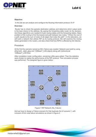
At the first the scenario named as NO_Failure was created. Network was build by using
ethernet4_ slip8_gtwy and 100BaseT_LAN objects along with bidirectional
100BaseT_LAN links.
After completion router configuration, remaining LANs were added. Then the statistics
were chosen to realize the performance of the RIP protocol. Then simulation process
was performed. The designed figure is given below :
Figure-1 RIP Network (No_Failure)
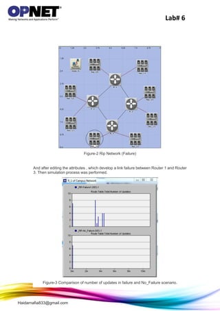
And we have to design a Failure scenario for that duplicate the of scenario 1, with
inclusion of link node failure simulations as shown in figure-2.
Lab# 6
Haidarnafia833@gmail.com
Figure-2 Rip Network (Failure)
And after editing the attributes , which develop a link failure between Router 1 and Router
3. Then simulation process was performed.
Figure-3 Comparison of number of updates in failure and No_Failure scenario.
Lab# 6
Haidarnafia833@gmail.com
The above figures shows the number updates those are sent by the router to its routing
table and when there is a failure to any other node connected to it as compared to the
situation when there is no failure in any of the link.
From the obtained graphs we can observe that for NO_Failure the number of updates
decrease from 13 to 4 with time by approximately , because the routing table has already
gathered information about neighboring nodes and after that only the information is
updated that means updates being sent are less. The scenario is similar for failure in
starting, but with time when the router senses link failure it again starts updating
information in it's routing table, the intensity of which is a little bit less then the time when
it sensed the failure.
RIP Trafic in No_Failure and Failure scenarios
Figure-4 Comparison of RIP traffic received in Failure and NO_Failure.
Figure-5 Comparison for RIP sent traffic in failure and No Failure Scenarios.
Lab# 6
Haidarnafia833@gmail.com
The above two graphs shows the comparison of RIP sent traffic in Failure and No_failure
scenario. The above graphs the first represents overlaid comparison and second one is
stacked comparison. The failure introduced into the RIP system changes the traffic sent
signals and also the traffic received signals.
EXERCISES
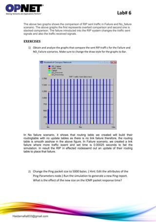
1) Obtain and analyze the graphs that compare the sent RIP traffi c for the Failure and
NO_Failure scenarios. Make sure to change the draw style for the graphs to Bar.
In No failure scenario, it shows that routing table we created will build their
routingtable with no update tables as there is no link failure therefore, the routing
table is smooth asshow in the above figure. In Failure scenario, we created a link
failure where more traffic issent and set time is 0.00025 seconds to fail the
simulation. In result the RIP in effected nodessend out an update of their routing
table to place that failure.
2) Change the Ping packet size to 5000 bytes. ( Hint: Edit the attributes of the
Ping Parameters node.) Run the simulation to generate a new Ping report.
What is the effect of the new size on the ICMP packet response time?
Lab# 6
Haidarnafia833@gmail.com
Lab# 6
Haidarnafia833@gmail.com
Conclusion:
By observing the results we can say that both No_failure and Failure scenarios are
having different results and as the time taken for updating the Routing Information
protocol is more for Failure scenario compared to NO_Failure scenario .Because the
system require acknowledgement and discard the packet and resend it that takes lots of
time to updating

More Related Content

Opnet lab 6 solutions

  • 1. Lab# 6 Haidarnafia833@gmail.com Opnet Lab 6 Solutions RIP: Routing Information Protocol A Routing Protocol Based on the Distance-Vector Algorithm Haider Nafaa Nseif ID:I201521051 1/3/2018 IRAQ
  • 2. Lab# 6 Haidarnafia833@gmail.com Objective: In this lab we can analyze and configure the Routing Information protocol. R.I.P Overview: Router has to check the packets destination address and determine which output ports is the best choice to the address. By seeing the forwarding table router do the decision. And these algorithms are needed to build routing tables and the forwarding tables. Basic problem of the routing to find the lowest-cost path between two nodes," Where the cost of a path equals to the sum of costs of all edges that make the path". In this laboratory, we will build a network that utilizes RIP as its routing protocol. We will examine the routing tables generated in the routers, and also check that how RIPS is affected by link failures. Procedure: At the first the scenario named as NO_Failure was created. Network was build by using ethernet4_ slip8_gtwy and 100BaseT_LAN objects along with bidirectional 100BaseT_LAN links. After completion router configuration, remaining LANs were added. Then the statistics were chosen to realize the performance of the RIP protocol. Then simulation process was performed. The designed figure is given below : Figure-1 RIP Network (No_Failure) And we have to design a Failure scenario for that duplicate the of scenario 1, with inclusion of link node failure simulations as shown in figure-2.
  • 3. Lab# 6 Haidarnafia833@gmail.com Figure-2 Rip Network (Failure) And after editing the attributes , which develop a link failure between Router 1 and Router 3. Then simulation process was performed. Figure-3 Comparison of number of updates in failure and No_Failure scenario.
  • 4. Lab# 6 Haidarnafia833@gmail.com The above figures shows the number updates those are sent by the router to its routing table and when there is a failure to any other node connected to it as compared to the situation when there is no failure in any of the link. From the obtained graphs we can observe that for NO_Failure the number of updates decrease from 13 to 4 with time by approximately , because the routing table has already gathered information about neighboring nodes and after that only the information is updated that means updates being sent are less. The scenario is similar for failure in starting, but with time when the router senses link failure it again starts updating information in it's routing table, the intensity of which is a little bit less then the time when it sensed the failure. RIP Trafic in No_Failure and Failure scenarios Figure-4 Comparison of RIP traffic received in Failure and NO_Failure. Figure-5 Comparison for RIP sent traffic in failure and No Failure Scenarios.
  • 5. Lab# 6 Haidarnafia833@gmail.com The above two graphs shows the comparison of RIP sent traffic in Failure and No_failure scenario. The above graphs the first represents overlaid comparison and second one is stacked comparison. The failure introduced into the RIP system changes the traffic sent signals and also the traffic received signals. EXERCISES 1) Obtain and analyze the graphs that compare the sent RIP traffi c for the Failure and NO_Failure scenarios. Make sure to change the draw style for the graphs to Bar. In No failure scenario, it shows that routing table we created will build their routingtable with no update tables as there is no link failure therefore, the routing table is smooth asshow in the above figure. In Failure scenario, we created a link failure where more traffic issent and set time is 0.00025 seconds to fail the simulation. In result the RIP in effected nodessend out an update of their routing table to place that failure. 2) Change the Ping packet size to 5000 bytes. ( Hint: Edit the attributes of the Ping Parameters node.) Run the simulation to generate a new Ping report. What is the effect of the new size on the ICMP packet response time?
  • 7. Lab# 6 Haidarnafia833@gmail.com Conclusion: By observing the results we can say that both No_failure and Failure scenarios are having different results and as the time taken for updating the Routing Information protocol is more for Failure scenario compared to NO_Failure scenario .Because the system require acknowledgement and discard the packet and resend it that takes lots of time to updating