Oresund
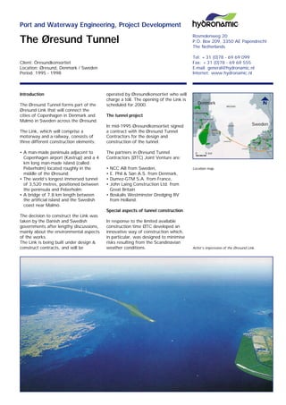
- 1. Rosmolenweg 20 P.O. Box 209, 3350 AE Papendrecht The Netherlands Tel: +31 (0)78 - 69 69 099 Fax: +31 (0)78 - 69 69 555 E-mail: general@hydronamic.nl Internet: www.hydronamic.nl Client: Ãresundkonsortiet Location: Ãresund, Denmark / Sweden Period: 1995 - 1998 Port and Waterway Engineering, Project Development The Ãresund Tunnel Location map. Artistâs impression of the Ãresund Link. Introduction The Ãresund Tunnel forms part of the Ãresund Link that will connect the cities of Copenhagen in Denmark and MalmÃķ in Sweden across the Ãresund. The Link, which will comprise a motorway and a railway, consists of three different construction elements: âĒ A man-made peninsula adjacent to Copenhagen airport (Kastrup) and a 4 km long man-made island (called Peberholm) located roughly in the middle of the Ãresund; âĒ The worldâs longest immersed tunnel of 3,520 metres, positioned between the peninsula and Peberholm; âĒ A bridge of 7.8 km length between the artificial island and the Swedish coast near MalmÃķ. The decision to construct the Link was taken by the Danish and Swedish governments after lengthy discussions, mainly about the environmental aspects of the works. The Link is being built under design & construct contracts, and will be operated by Ãresundkonsortiet who will charge a toll. The opening of the Link is scheduled for 2000. The tunnel project In mid-1995 Ãresundkonsortiet signed a contract with the Ãresund Tunnel Contractors for the design and construction of the tunnel. The partners in Ãresund Tunnel Contractors (ÃTC) Joint Venture are: âĒ NCC AB from Sweden, âĒ E. Phil & SÃļn A.S. from Denmark, âĒ Dumez-GTM S.A. from France, âĒ John Laing Construction Ltd. from Great Britain âĒ Boskalis Westminster Dredging BV from Holland. Special aspects of tunnel construction In response to the limited available construction time ÃTC developed an innovative way of construction which, in particular, was designed to minimise risks resulting from the Scandinavian weather conditions. 0 5 km Denmark Sweden
- 2. Multi Purpose Pontoon MPP. Tunnel element before immersion. Typical design features: âĒ Simultaneous construction of two tunnel segments on two covered production lines, in a casting yard at land level âĒ Casting of a 2,500 m3 segment in one continuous 24 hour cast âĒ Sluicing the completed elements down from land to sea level by use of a lock âĒ Preparation of a gravel bed foundation for tunnel elements in the dredged trench, using the Boskalis scradingÂŪ method âĒ Use of satellite navigation for transport and for tunnel element immersion On behalf of ÃTC, Hydronamic executed various engineering tasks during the design phase of the project: âĒ Design of the gravel bed foundation, including construction method âĒ Design of the survey system to verify acceptability of the gravel bed âĒ Design of the stone protection layer on top of the tunnel, including required filter construction âĒ Supervision of model tests in the local hydraulic laboratories (DHI) âĒ Development of immersion equipment âĒ Development of the QA (work-) procedures for the marine works âĒ Development of the Multi Purpose Pontoon (MPP) for ÃTC. The design The tunnel cross-section consists of two dual-carriage motorway bores, with a service annex escape gallery in between, and two single-track railway bores. The total width of the tunnel is 38.65 m, with a height of 8.55 m. Twenty 176 m long elements will form a straight tunnel of 3,520 m. The maximum construction depth is approx. 22 m below water, while the future navigation depth over the tunnel will be dredged to -10 m. A complicating factor at this site is the behaviour of the current. There is hardly any tidal variation but a very complex current system exists in the Little Belt, Great Belt and the Ãresund. The most accurate current prediction system available can only predict up to 12 hrs. ahead. This limits the flexibility of operations, necessitating strict management based on step-by-step, âgo or no goâ decision- making. Multi Purpose Pontoon The purpose designed and built Multi Purpose Pontoon has the following tasks: âĒ Cleaning the dredged trench âĒ Construction of the gravel bed âĒ Survey of the gravel bed for acceptance âĒ Repair and maintenance of the gravel bed, when required âĒ Backfill of trench with sand and stone material âĒ Construction of filter and armour layers Basically all functions are performed with a fall-pipe, moving sideways along the pontoon, while material is supplied on a conveyer belt system. Depending on the task to be performed different tools are fixed to the bottom of the fall-pipe, namely a gravel scrading unit, sand chute or vortex clean-up unit, all purpose designed and built. The survey Boskalis, in co-operation with Geocon Holland Inc. are responsible for the immersion survey works. Transport and immersion of elements are fully controlled through DGPS navigation. Coordinates of antennas are, via the command tower and access shaft, transferred down to the element, providing very accurate placement information. For leveling of the gravel bed a horizontally rotating laser-plane is established, to provide even greater accuracy. Ground bed sounding is made with two rows of five 1 Mhz. transducers, placed on the sides of the scrading unit. On line corrections are implementated for water salinity variations. Transport route of the tunnel elements. 0 1 2 3 4 5 km


