Permanent Magnet Brushless DC Motor brief
ŌĆóDownload as PPSX, PDFŌĆó
0 likesŌĆó9 views

PMBLDC


Permanent Magnet Brushless DC Motor brief
- 1. November 26, 2024 1 Permanent Magnet materials ŌĆō Minor hysteresis loop and recoil line ŌĆō Magnetic Characteristics ŌĆō Permeance coefficient ŌĆōPrinciple of operation ŌĆō Types ŌĆō Magnetic circuit analysis ŌĆō EMF and torque equations ŌĆō Commutation ŌĆō Power Converter Circuits and their controllers ŌĆō Motor characteristics and control ŌĆō Applications. PERMANENT MAGNET BRUSHLESS D.C. MOTORS
- 2. November 26, 2024 2 PMBLDC MOTORS Magnetic circuit analysis, Magnetic characteristics and Permeance coefficient
- 3. November 26, 2024 3 MAGNETIC CIRCUIT ANALYSIS ŌĆó The basic calculation method of a magnetic circuit is the same as is used in a basic electrical analysis using OhmŌĆÖs Law. ŌĆó The total magnetic flux ├Ė (analogous to electric current), magneto-motive force F (analogous to voltage), and magnetic reluctance R (analogous to electrical resistance) are related as shown in below.
- 4. November 26, 2024 4 ŌĆó In magnetic circuit calculations, it is more common to use the magnetic permeance P, which is the reciprocal to reluctance R. ŌĆó Using permeance instead of reluctance, the total flux equation is changed as shown in below.
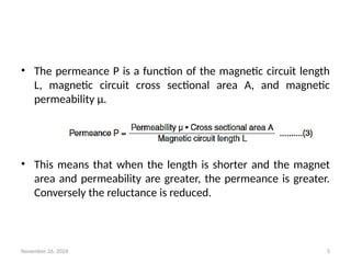
- 5. November 26, 2024 5 ŌĆó The permeance P is a function of the magnetic circuit length L, magnetic circuit cross sectional area A, and magnetic permeability ╬╝. ŌĆó This means that when the length is shorter and the magnet area and permeability are greater, the permeance is greater. Conversely the reluctance is reduced.
- 6. November 26, 2024 6 Magnetomotive force loss coefficient ŌĆśfŌĆÖ ŌĆó The magnetomotive force loss coefficient f is the ratio of the total magnetomotive force Ft and the magnetomotive force in the air gap Fg for a given magnetic circuit. ŌĆó The total magnetomotive force Ft in the magnetic circuit is determined as the product of the magnetic field strength Hd at the operating point, and the length of the magnet Lm. (4)
- 7. November 26, 2024 7 ŌĆó The magnetomotive force in the air gap Fg is given as the product of the magnetic field strength of the air gap Hg, and the length of the air gap Lg. ŌĆó Thus equation (4) becomes as follows (5)
- 8. November 26, 2024 8 Leakage coefficient (Žā) ŌĆó The leakage coefficient is the ratio of the total magnetic flux ├Ėt generated from the magnet in a given circuit and the flux found in the air gap ├Ėg. ŌĆó The total magnetic flux generated in a magnet ├Ėt is given as the accumulation of flux density at the operating point Bd over the cross sectional area of the magnet Am and the magnetic flux in the air gap ├Ėg is given as the accumulation of flux density Bg over the area of the air gap Ag. (6)
- 9. November 26, 2024 9 ŌĆó Equation (6) now becomes (7)
- 10. November 26, 2024 10 Permeance coefficient (Pc) ŌĆó The permeance coefficient is used to design a permanent magnet application with a B-H curve. ŌĆó This is defined as the ratio of flux density Bd and magnetic field strength Hd of the operating point, and equation becomes: (8)
- 11. November 26, 2024 11 ŌĆó The relationship is shown in figure 1 below:
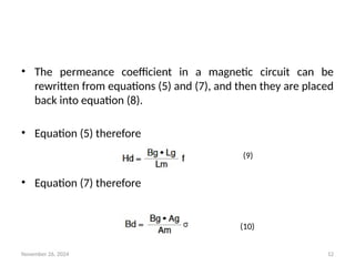
- 12. November 26, 2024 12 ŌĆó The permeance coefficient in a magnetic circuit can be rewritten from equations (5) and (7), and then they are placed back into equation (8). ŌĆó Equation (5) therefore ŌĆó Equation (7) therefore (9) (10)
- 13. November 26, 2024 13 (11)
- 14. November 26, 2024 14 Fig. Operating values of Hm, Bm for different values of PC
- 15. November 26, 2024 15 PMBLDC MOTORS EMF AND TORQUE EQUATIONS
- 16. November 26, 2024 16 Equivalent Circuit and General Equations ŌĆó The per phase equivalent circuit is shown in Fig.1 as following, where ╬╗m is the flux linkage of stator winding per phase due to the permanent magnet. ŌĆó For steady state conditions, assuming v and e are sinusoidal at frequency Žē, the equivalent circuit becomes the one shown in Fig.2, where X=ŽēL, and V, I, E, and ╬╗m are phasors with rms amplitudes.
- 17. November 26, 2024 17
- 18. November 26, 2024 18 ŌĆó The steady state circuit equation can be written as ŌĆó Assuming that ŽēL << R, For a maximum mechanical power at a given speed, I and E are in phase.
- 19. November 26, 2024 19 ŌĆó A brushless dc motor has position feedback from the rotor via Hall devices, optical devices, encoder etc. to keep a particular angle between V And E, since E is in phase with rotor position, and V is determined by the inverter supply to the motor. ŌĆó Assuming that ŽēL << R, when I is in phase with E, V will also be in phase with E. Thus the circuit can be analyzed using magnitudes of E,V, and I as if it were a dc circuit.
- 20. November 26, 2024 20 ŌĆó But first note that when E and I are in phase, the motor mechanical power output (before friction, windage, and iron losses) i.e. the electromagnetic output power is
- 21. November 26, 2024 21
- 22. November 26, 2024 22
- 23. November 26, 2024 23 UNIT 4 ŌĆō PMBLDC MOTORS COMMUTATION
- 24. November 26, 2024 24 COMMUTATION ŌĆó Brushless motors rely on semiconductor switches to turn stator windings on and off at the appropriate time. ŌĆó The process is called electronic commutation ŌĆó Commutation with electronics has large scope of capabilities and flexibility.
- 25. November 26, 2024 25 ŌĆó In this motor, the mechanical "rotating switch" or commutator is replaced by an external electronic switch synchronised to the rotor's position. ŌĆó Brushless direct current electric motors, or BLDC motors for short, are electronically commutated motors powered by a DC electric source via an external motor controller. ŌĆó Put simply, commutation is the process of switching the current in the motor phases to generate motion.
- 26. November 26, 2024 26 BLDC Motor commutation ŌĆó Before dwelling too far into feedback options for BLDC motors, it is important to understand why they are necessary. ŌĆó BLDC motors come in single phase, 2-phase, and 3-phase configurations; the most common configuration being 3- phase. ŌĆó The number of phases matches the number of windings on the stator while the rotor poles can be any number of pairs depending on the application.
- 27. November 26, 2024 27 ŌĆó Because the rotor of a BLDC motor is influenced by the revolving stator poles, the stator pole position must be tracked in order to effectively drive the 3 motor phases. ŌĆó Hence, a motor controller is used to generate a 6-step commutation pattern on the 3 motor phases. ŌĆó These 6-steps, or commutation phases, move an electromagnetic field which causes the permanent magnets of the rotor to move the motor shaft.
- 28. November 26, 2024 28
- 29. November 26, 2024 29 ŌĆó This is where feedback technology becomes important; for the controller to maintain accurate control of the motor, it must always know the exact position of the stator in relation to the rotor. ŌĆó Any misalignment or phase shift in the expected and actual position may result in undesirable behavior and a decline in performance. ŌĆó There are many ways to achieve this feedback for the commutation of BLDC motors, but the most common are Hall effect sensors, encoders, or resolvers.
- 30. November 26, 2024 30 ŌĆó Position feedback ŌĆó Since the inception of the brushless motor, Hall-effect sensors have been the workhorse for commutation feedback. ŌĆó For 3-phase control, only three sensors are required, Hall sensors are embedded into the stator of the motor to detect rotor positon, which is used to switch the transistors in the 3- phase bridge to drive the motor.
- 31. November 26, 2024 31 ŌĆó The three Hall-effect sensor outputs are commonly noted as the U, V, and W channels.
- 32. November 26, 2024 32 ŌĆó The commutation sequence is shown in the following video url ŌĆó https://www.youtube.com/watch?time_continue=4&v=6ELRk eEwlDw (Students are advised to go through the video link for greater clarity and understanding)
- 33. November 26, 2024 33