Permeability test
- 1. University of Sulaimani College of Engineering Civil Engineering Department (Soil Mechanics Lab) Name of the Test: Constant Head Permeability Test Test No. : Students Name: 1- Raz Azad Abdullah 2- Rawezh saady 3- Zhyar Abubakir Group & Sub-Group: A1-A6 Date of the Test:
- 2. Introduction: The constant head permeability test is a laboratory experiment conducted to determine the permeability of soil. The soils that are suitable for these tests are sand and gravels. Soils with silt content cannot be tested with this method. The test can be employed to test granular soils either reconstituted or disturbed. The passage of water through porous material is called seepage. A material with continuous voids is called a permeable material. Hence permeability is a property of a porous material which permits passage of fluids through inter connecting conditions. There are two general types of permeability test methods that are routinely performed in the laboratory: 1) Constant head test method. 2) Falling head test method. The constant head test method is used for permeable soils (k>10-4 cm/s) and the falling head test is mainly used for less permeable soils (k<10-4 cm/s).
- 3. Purpose of the Test: The purposeof constant head permeability test is to determine the coefficient of permeability of a soil. Coefficient of permeability helps in solving issues related to: 1. Yield of water bearing strata. 2. Stability of earthen dams. 3. Embankments of canal bank. 4. Seepage in earthen dams. 5. Settlement Issues. Apparatus: 1. Constant head permeameter. 2. Graduated cylinder (250 cc or 500 cc). 3. Balance, sensitive up to 0.lg. 4. Thermometer, sensitive up to 0.1 °C. 5. Rubber tubing. 6. Stop watch.
- 4. Procedure: (1) Measure the initial mass of the pan along with the dry soil (M1). (2) Remove the cap and upper chamber of the permeameter by unscrewing the knurled cap nuts and lifting them off the tie rods. Measure the inside diameter of upper and lower chambers. Calculate the average inside diameter of the permeameter (D). (3) Place one porous stoneon the inner supportring in the base of the chamber then place a filter paper on top of the porous stone. (4) Mix the soil with a sufficient quantity of distilled water to prevent the segregation of particle sizes during placement into the permeameter. Enough water should be added so that the mixture may flow freely. (5) Using a scoop, pourthe prepared soil into the lower chamber using a circular motion to fill it to a depth of 1.5 cm. A uniform layer should be formed. (6) Use the tamping device to compactthe layer of soil. Use approximately ten rams of the tamper per layer and provide uniform coverage of the soil surface. Repeat the compaction procedureuntil the soil is within 2 cm. of the top of the lower chamber section. (7) Replace the upper chamber section, and donâtforget the rubber gasket that goes between the chamber sections. Be careful not to disturb the soil that has already
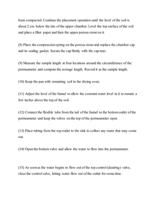
- 5. been compacted. Continue the placement operation until the level of the soil is about 2 cm. below the rim of the upper chamber. Level the top surface of the soil and place a filter paper and then the upper porous stoneon it. (8) Place the compressionspring on the porous stone and replace the chamber cap and its sealing gasket. Secure the cap firmly with the cap nuts. (9) Measure the sample length at four locations around the circumference of the permeameter and compute the average length. Record it as the sample length. (10) Keep the pan with remaining soil in the drying oven. (11) Adjust the level of the funnel to allow the constant water level in it to remain a few inches above the top of the soil. (12) Connect the flexible tube from the tail of the funnel to the bottom outlet of the permeameter and keep the valves on the top of the permeameter open. (13) Place tubing from the top outlet to the sink to collect any water that may come out. (14) Open the bottom valve and allow the water to flow into the permeameter. (15) As soonas the water begins to flow out of the top control (deairing) valve, close the controlvalve, letting water flow out of the outlet for some time.
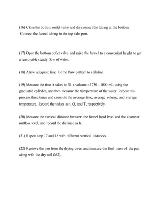
- 6. (16) Close the bottom outlet valve and disconnect the tubing at the bottom. Connect the funnel tubing to the top side port. (17) Open the bottom outlet valve and raise the funnel to a convenient height to get a reasonable steady flow of water. (18) Allow adequate time for the flow pattern to stabilize. (19) Measure the time it takes to fill a volume of 750 - 1000 mL using the graduated cylinder, and then measure the temperature of the water. Repeat this process three times and compute the average time, average volume, and average temperature. Record the values as t, Q, and T, respectively. (20) Measure the vertical distance between the funnel head level and the chamber outflow level, and record the distance as h. (21) Repeat step 17 and 18 with different vertical distances. (22) Remove the pan from the drying oven and measure the final mass of the pan along with the dry soil (M2).
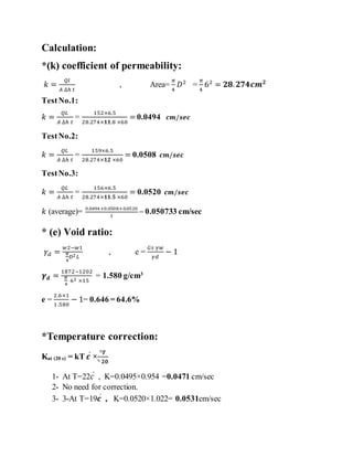
- 7. Calculation: *(k) coefficient of permeability: ð = ðð ðī ââ ðĄ , Area= ð 4 ð·2 = ð 4 62 = ðð. ððððð ð TestNo.1: ð = ððŋ ðī ââ ðĄ = 152Ã6.5 28.274Ãðð.8 Ã60 =0.0494 ðð/ððð TestNo.2: ð = ððŋ ðī ââ ðĄ = 159Ã6.5 28.274Ãðð Ã60 = 0.0508 ðð/ððð TestNo.3: ð = ððŋ ðī ââ ðĄ = 156Ã6.5 28.274Ãðð.ð Ã60 = 0.0520 ðð/ððð ð (average)= 0.0494+0.0508+0.0520 3 = 0.050733 cm/sec * (e) Void ratio: ðū ð = ðĪ2âðĪ1 ð 4 ð·2 ðŋ , e = ðšð ðūðĪ ðūð â 1 ðļ ð = 1872â1202 ð 4 62 Ã15 = 1.580 g/cm3 e = 2.6Ã1 1.580 â 1= 0.646 = 64.6% *Temperature correction: Kat (20 c) = kT ðÍĶ à áķŊðŧ áķŊ ðð 1- At T=22ðÍĶ , K=0.0495Ã0.954 =0.0471 cm/sec 2- No need for correction. 3- 3-At T=19ðÍĶ , K=0.0520Ã1.022= 0.0531cm/sec
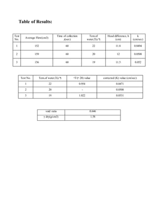
- 8. Table of Results: Test No. Tem.of water,T(c^ÍĶ) áķŊT/(áķŊ 20) value corrected (K) value (cm/sec) 1 22 0.954 0.0471 2 20 - 0.0508 3 19 1.022 0.0531 Test No. Average Flow(cm3) Time of collection ,t(sec) Tem.of water,T(c^ÍĶ) Head difference, h (cm) k (cm/sec) 1 152 60 22 11.8 0.0494 2 159 60 20 12 0.0508 3 156 60 19 11.5 0.052 void ratio 0.646 Îģ dry(g/cm3) 1.58
- 9. Discussion and Conclusion: Permeability can be defined as the ability of a porous medium to allow the flow of a fluid through it, typically expressed as the coefficient of permeability. This property is necessary for the calculations such as seepage through earth dams or under sheet pile walls, the seepage rate from waste storage facilities, landfills, ponds, etc. and the rate of settlement of clayey soil deposits. In this experiment after calculation and observing the results we got that, our soil sample that has being used in the test, had dry unite weight of (1.58g/cm3) with void ratio of ( ) and its coefficient of permeability was(0.0471cm/sec )for first trail,(0.0508cm/sec for second and 0.0531 cm/sec) for third trial. However, the mean value of coefficient of permeability for our soil sample was (0.50733 cm/sec); according to ASTM classification our sand, is coarse sand becausethe k is in range of (0.01-1). The factors that affect permeability: ï· The porosity of the soil. ï· The particle-size distribution ï· The shape and orientation of soil particles. ï· The degree of saturation/presence of air. ï· The type of cation and thickness of adsorbed layers associated with clay mineral. ï· The viscosity of the soil water, which varies with temperature. The greater pore size of soil is more permeability than the soil with smaller pore size .From value of k, we can classify the type of soil that we use is silty sands or silty clays and this types of soil is not suitable for drainage system. The knowledge of permeability is important for the following engineering problems: ï· To find out the rate of consolidation and settlement of a saturated soil under load.
- 10. ï· To compare the permeability of two soils or in comparing the permeability of a soil in horizontal and vertical directions in designing of projects where vertical sand drains are used. ï· Investigating problems involving pumping seepage of water for underground constructions. ï· To estimate ground water flow. ï· To calculate the uplift pressure and piping. Errors that may occurdue to: ï· Parallax error is occurred where the observerâs eyes are not perpendicular to the scale while reading the height to overcome this error, the observers eye must be 90 degree perpendicular to the water level in order to get the accurate measurement. ï· If the soil was saturated before the test or the equipment was wet. ï· The flow should be laminar and in a steady state condition. To conclude this experiment has determined the permeability of the sample by constant head method, and according to Darcyâs law the sample was determined to be coarse sand. References: ï· https://wenku./view/aad571313968011ca30091e2 ï· Soil Mechanics Laboratory Manual. ï· https://www.scribd.com/document/320529799/
