際際滷

際際滷Share a Scribd company logo
SAMPLE DESIGN
of
PIER
Example : Checking of Pier suitable for 18.3 metre
span plate girder for MBG loading.
Data :
i) Super structure - Plate girder
ii) Span & weight including
track
- 18.3 metre
29.87 t
iii) Over all length of girder - 19.65 m
iv) Depth of girder - 1930 mm
v) Type of bearing - Sliding bearing
vi) Distance between centre of
bearing & centre of pier
- 0.2 m
vii) Height of bearing - 50 mm
viii) Material of const. - M-10 concrete
ix) Unit wt. of mass concrete - 2200 to 2400 kg/m3
x) Loading standard - MBG  1987
xi) Angle of internal friction &
wt. of soil
- 35, 1760 kg/m3
xii) Track structure on
approach
- 60 kg rail resting on
PSC sleeper
xiii) Seismic zone - Zone ( V)
Pier design.pptVVVVVVVVVVVVVVVVVVVVVVVVVV
CHECKING OF PIER SPAN 18.3m
FOR MBG LOADING - 1987
AREA AT THE TOP :
= 3.66 x 1.5 +(/4) x 1.52
= 7.257 m2
AREA AT 1m DEPTH FROM THE TOP :
= 3.66 x 1.537 + (/4) x 1.5372
= 7.481 m2
WIDTH OF SECTION AT 1.5m DEPTH = 1.5705m
AREA =3.66 x1.5705+ (/4) x 1.57052
= 7.685 m2
VOLUME OF BED BLOCK = 3.338 m3
WEIGHT OF BED BLOCK = 3.338 x 2.2 = 7.344 t
VOLUME OF PIER BETWEEN BED BLOCK
AND 1m DEPTH
=(7.257+7.481) x 0.54 / 2
= 3.979 m3
VOLUME OF PIER BETWEEN 1m AND 1.5m
DEPTH
=(7.481+ 7.685) x 0.5 / 2
= 3.792 m3
AREA OF PIER AT 12m DEPTH :
= 2.282 x 3.66 + (/4) x 2.2822
= 12.442 m2
VOLUME OF PIER BETWEEN 1.5m AND 12m
DEPTH
= 3.894 + (12.442 + 7.891) x 10 / 2
= 105.559 m3
BUOYANCY EFFECT : 105.559t x 0.15 5.10.2 SSC
TOTAL WEIGHT OF PIER AT 12m DEPTH
INCLUDING BUOYANCY EFFECT :
= Bed Block +Pier below bed block upto 1.5m+
Wt between 1.5m to 12m depth including
buoyancy
= 3.338 x 2.2 + (3.979 + 3.792) x 2.4 + (105.559
x2.4)  105.559 x 0.15
= 263.502 t
To be checked for single span & double span
loading conditions
Clause 5.3 c
SSC
LIVE LOAD :
SINGLE SPAN LOADED CONDITION
LOADED LENGTH = 19.65
EUDL FOR S.F.
= (231.64  222.29) x 0.65 + 222.29
= 227.72 t
5.3 c SSC
Appendix XX
III
BR
REACTION = 227.72/2 = 113.86 t
DOUBLE SPAN LOADED CONDITION
EUDL FOR B.M.
L = 2 x 19.8 = 39.6 m
EUDL for BM =(376.63-360.53) x 1.6/2 + 360.53
= 373.41 t
5.3 c SSC
Appendix XX
III
BR
REACTION = 373.41 / 2 = 186.7 t
LONGITUDINAL FORCE
Single Span :
TE1
= 75.0 BF1
= 50.6 Appendix XX
IV
BR
With Dispersion and Distribution 2.8.3.2 BR
TE1
= ( 75  75 x 0.25) x 0.4 = 22.5 2.8.2.4.1 BR
BF1
= ( 50.6  16.0 ) x 0.4 = 13.84
For Seismic condition 50% L.F. 2.8.5 BR
TE1
=22.5 / 2 = 11.25 t
BF1
= 13.84 / 2 = 6.92 t
DOUBLE SPAN :
With Dispersion and Distribution
TE2
= 126.0 BF2
= 80 Appendix XX
IV
BR
TE2
= 126 x 0.75 x 0.4 = 37.8 t
BF2
= 80 x 0.75 x 0.4 = 24.0 t
For Seismic condition 50% L.F. 2.8.5 BR
TE2
= 37.8 / 2 = 18.9 t
BF2
= 24.0 / 2 = 12.0 t
FORCE DUE TO WATER CURRENT :
Water Current flowing parallel to pier
P = KAV2
= 35 x (1.5705 + 2.282) x 10.5 x 32
/ 2 x 1000
= 6.371 t
Clause
5.9.2.1
5.9.2.2 (Tabl
e 4)
SSC
Water Current flowing perpendicular to Pier
=35x(1.5705+2.282)+(3.66+2.282)x10.5x32
/2x5x1000
= 3.695 t
Clause 5.9.2.
4
SSC
Moment at the Base along X-X direction i.e.
perpendicular to Pier
= 6.371 x 10.5 x 2 / 3 = 44.597 t-m
WIND LOAD :
Projected area of Girder & track
= (1.930 + 0.172 + 0.152) 19.65
= 2.254 x 19.65 = 43.45 m2
Since spacing of girder is not exceeding full
depth Hence Factor = 0.25
2.11.3.1(a)
BR
Projected Area of Girder
= 1.25 x 43.45 = 54.3 m2
Lever Arm from C.G. to top of Bed Block
= 2.254 / 2 + 0.05 = 1.177
Projected Area of Train (PAT)
= ( 4.115  0.6) 19.67 = 69.14 m2
2.11.3.1(b)
Note 1
BR
Lever Arm from C.G. to Top of Bed Block
= 3.515 / 2 + 0.6 + 2.254 +0.05 = 4.641 m
SECTIONAL PROPERTIES AT 12m DEPTH
AREA = (/4) x 2.2822
+ 3.66 x 2.282
= 12.442 m2
Ixx = (1 / 12) x 3.66 x 2.2823
+ (/4) x 2.2824
= 4.956 m4
Iyy = (1 / 12) x 2.282x 3.66 3
+ 0.2196 x 1.1414
+  x 1.141 x (0.5x3.66+0.42x1.141)2
= 31.592 m4
SINGLE SPAN LOADED CONDITION :
D.L. OF GIRDER + TRACK = 29.87
L.L. REACTION = 108.98
Wt. OF PIER = 263.502
402.352 t
MOMENT ALONG X-X AXIS
DUE TO L.F. = 22.5(12+0.05) = 271.125
DUE TO WATER CURRENT = 25.865
DUE TO L.L. = 108.98 x 0.2 = 21.796
318.786 t-n
MOMENT ALONG Y-Y AXIS
DUE TO WATER CURRENT = 44.597 t-m
STRESSES :
= (402.352/12.442)  (318.786/4.956)x(2.282/2)
 (44.597/31.592)x(3.66/2)
= 32.338  73.393  2.583
Max = 108.314 t/m2
Min = - 43.639 t/m2
NORMAL LOAD + OCCASSIONAL LOAD (W.L.)
DL. OF GIRDER + TRACK = 29.870
LIVE LOAD REACTION = 108.98
Wt. OF PIER = 263.502
402.352
MOMENT ALONG X-X AXIS
DUE TO LF = 22.5 ( 12 + 0.05) = 271.125
DUE TO WATER CURRENT = 25.865
DUE TO LL = 21.796
318.786
MOMENT ALONG Y-Y AXIS
DUE TO WATER CURRENT = 44.597
DUE TO WIND ON GIRDER
54.3x(1.177+12) 0.15 = 107.327
DUE TO WIND ON TRAIN
69.1 / 2 (4.641=12) x 0.15 = 86.242
238.166
(on one span only)
STRESSES :
= (402.352/12.442)  (318.786/4.956)x(2.282/2)
 (238.166/31.592)x(3.66/2)
= 32.338  73.393  13.796
Max = 119.527 t/m2
Min = -54.945 t/m2
DOUBLE SPAN LOADED CONDITION :
DL OF GIRDER + TRACK = 29.87
LL REACTION = 176.79
Wt. OF PIER = 263.502
470.162 t
MOMENT ALONG X-X AXIS
DUE TO L.F. = 30.00(12+0.05) = 361.50
DUE TO WATER CURRENT = 25.865
387.36 t-m
MOMENT ALONG Y-Y AXIS
DUE TO WATER CURRENT = 44.597 t-m
STRESSES :
= (470.162/12.442)  (387.36/4.956)x(2.282/2)
 (44.597/31.592)x(3.66/2)
= 37.788  88.95 2.583
Max = 37.788+88.95+2.583 = 129.31 t/m2
Min = -53.75 t/m2
NORMAL + OCL (DOUBLE SPAN LOADED CONDITION)
DL OF GIRDER + TRACK = 29.870
LL REACTION = 176.790
Wt. OF PIER = 263.502
470.162 t
MOMENT ALONG X-X AXIS = 387.36 t-m
MOMENT ALONG Y-Y AXIS :
DUE TO WATER CURRENT = 44.597
DUE TO WIND ON TRAIN
69.1(4.641+12.0) = 172.484
DUE TO WIND OF GIRDER
54.3(1.177+12.0) = 107.327
324.408 t-m
STRESSES :
= (470.162/12.442)  (387.36/4.956)x(2.282/2)
 (324.408/31.592)x(3.66/2)
= 37.788  89.18  18.792
Max = 145.76 t/m2
Min = -70.18 t/m2
SEISMIC & HYDRODYNAMIC FORCE
When the Horizontal Seismic acting parallel to traffic
SEISMIC HORIZONTAL COEFFICIENT
h
= 硫 I 
I = 1.0
硫 = 1.2
 = 0.08
2.12.4.2 BR
2.12.4.4 BR
2.12.4.3 BR
(Table)
2.12.3.3 BR
h
= 1.2 x 0.08 x1 = 0.096
HYDRO DYNAMIC FORCES
F = Ce
h
Wex
Ce
= Co-efficient taken from table 5 based on H/R
H / R = 10.5 / (5.942 / 2) = 3.534
Ce = (0.735  0.675) x 0.534 + 0.675 = 0.707
F = 291.206 x 0.096 x 0.707 = 19.765 t
h = H
C 1
= H / h = 10.5 / 10.5 = 1.0
C 2
= 1.0 C 3
= 1.0 C 4
= 0.4286
LEVER ARM = C4
H = 0.428 x 10.5 = 4.494
MOMENT = 19.765 x 4.494 = 88.824 t-m
Wex
= (/4) x 5.9422
x 10.5 x 1 = 291.206 t
SEISMIC FORCE IN HORIZONTAL DIRECTION
S.
No
.
DESCRIPTION MASS
h
SEISMI
C
FORCE
LEVE
R ARM
MOMENT
ABOUT
X-X
1 GIRDER +
TRACK
29.87 0.096 2.8675 13.177 37.79
2 BED BLOCK 7.344 0.096 0.705 11.77 8.298
3 Wt. OF PIER
BELOW BED
BLOCK
271.992
without
Bouancy
5.12.2(a)
SSC
0.096 26.111 5.77 150.662
196.752
L.L ignored in case of parallel to traffic 2.12.6 BR
SEISMIC FORCE IN VERTICAL DIRECTION
S.
No.
DESCRIPTION MASS
v
SEISMIC
FORCE
1 GIRDER + TRACK 29.87 0.096/2 1.434
2 BED BLOCK 7.344 0.096/2 0.352
3 Wt. OF PIER BELOW
BED BLOCK
271.992 0.096/2 13.056
4 LIVE LOAD ( SS ) 108.98 0.096/2 5.231
20.073
5 LIVE LOAD ( DS ) 176.79 0.096/2 8.486
When the Horizontal Seismic acting perpendicular to traffic
HYDRO DYNAMIC FORCES
F = Ce h Wex
H / R = 10.5 / (2.282 / 2) = 9.202
Ce = 0.730
Wex
= (/4) x 2.2822
x 10.5 x 1 = 42.945
F = 42.945 x 0.096 x 0.730 = 3.03 t
LEVER ARM = 0.428 x 10.5 = 4.494
MOMENT = 3.03 x 4.494 = 13.618 t-m
HORIZONTAL SEISMIC FORCE
S.
No
.
DESCRIPTION MASS
h
SEISMI
C
FORCE
LEVE
R ARM
MOMEN
T
ABOUT
X-X
1 GIRDER +
TRACK
29.87 0.09
6
2.868 13.177 37.792
2 BED BLOCK 7.344 0.09
6
0.705 11.77 8.298
3 Wt. OF PIER
BELOW BED
BLOCK
271.99
2
0.09
6
26.11 5.77 150.662
50% LIVE LOAD
( S.S.)
2.12.6 BR
108.98/
2
0.09
6
5.231 16.641 87.049
283.801
50% LIVE LOAD
( D.S.)
176.79/
2
0.09
6
8.486 16.641 141.24
337.992
VERTICAL EFFECT OF SEISMIC FORCE
S.
No
.
DESCRIPTION MASS
h
SEISMIC
FORCE
1 GIRDER + TRACK 29.87 0.048 1.434
2 BED BLOCK 7.344 0.048 0.352
3 Wt. OF PIER
BELOW BED
BLOCK
271.992 0.048 13.056
4 LIVE LOAD( S.S.) 108.98 0.048 5.231
20.073
D.S. LIVE LOADED
CONDITION LIVE
LOAD
176.79 0.048 8.486
23.328
STRESS CALCULATIONS :
SINGLE SPAN When the Seismic Force acting parallel to Traffic
DL OF GIRDER + TRACK = 29.870
LL REACTION = 108.98
Wt. OF PIER = 263.502
LESS SEISMIC FORCE = - 20.073
382.279 t
MOMENT ABOUT X-X AXIS
DUE TO 50% L.F. = ( 22.5 x 0.5) x 12.05 = 135.563 t-m
DUE TO WATER CURRENT = 25.865 t-m
DUE TO L.L. = 21.796 t-m
DUE TO SEISMIC FORCE = 196.752
DUE TO HYDRODYNAMIC FORCE = 088.824
468.800 t-m
MOMENT ABOUT Y-Y AXIS
DUE TO WATER CURRENT = 44.597 t-m
STRESSES
= (382.279/12.442)  (468.80/4.956)x(2.282/2)
 (44.597/31.592)x(3.66/2)
= 30.725  107.93  2.583
Max. = 30.725 + 107.93 + 2.583
= 141.238 t/m2
Max. Stress shall be 144.5 t/m2
if vertical component of seismic
force is taken downwards.
Min. = 30.725 - 107.93  2.583
= ( -) 79.788 t/m2
When the Seismic Force acting parallel to Traffic :
DL OF GIRDER + TRACK = 29.870
LL REACTION = 108.98
Wt. OF PIER = 263.502
LESS SEISMIC FORCE = - 20.073
382.279 t
MOMENT ABOUT X-X AXIS
DUE TO 50% L.F. = ( 22.5 x 0.5) x 12.05 = 135.563 t-m
DUE TO WATER CURRENT = 25.865 t-m
DUE TO L.L. = 21.796 t-m
183.224 t-m
MOMENT ABOUT Y-Y AXIS
DUE TO WATER CURRENT = 44.597 t-m
DUE TO SEISMIC FORCE = 283.801 t-m
DUE TO HYDRODYNAMIC FORCE = 13.618 t-m
TOTAL 342.016 t-m
STRESSES
= (382.279/12.442)  (183.224/4.956)x(2.282/2)
 (342.016/31.592)x(3.66/2)
= 30.725  42.183 19.812
Max. = 30.725 + 42.183 + 19.812
= 92.72 t/m2
Min. = 30.725  42.183  19.812 = ( -) 31.27 t/m2
DOUBLE SPAN :
When the Seismic Force acting parallel to traffic :
DL OF GIRDER + TRACK = 29.870
LL REACTION = 176.79
Wt. OF PIER = 263.502
LESS SEISMIC FORCE = - 23.328
446.834 t
MOMENT ABOUT X-X AXIS
DUE TO 50% L.F. = 15.00 x 12.05 = 180.75 t-m
DUE TO WATER CURRENT = 25.865 t-m
DUE TO SEISMIC FORCE = 196.752 t-m
DUE TO HYDRODYNAMIC FORCE = 88.824
492.191 t-m
MOMENT ABOUT Y-Y AXIS
DUE TO WATER CURRENT = 44.597 t-m
STRESSES
= (446.834/12.442)  (492.791/4.956)x(2.282/2)
 (44.597/31.592)x(3.66/2)
= 35.913  113.315  2.583
Max. = 35.913 + 113.315 + 2.583 = 151.811 t/m2
Min. = 35.913  113.315  2.583 = ( -) 79.985 t/m2
When the Seismic Force acting perpendicular to traffic :
DL OF GIRDER + TRACK = 29.870
LL REACTION = 176.79
Wt. OF PIER = 263.502
LESS SEISMIC FORCE = - 23.328
446.834 t
MOMENT ABOUT X-X AXIS
DUE TO 50% L.F. = 15.00 x 12.05 = 180.75 t-m
DUE TO WATER CURRENT = 25.865 t-m
1.t-m
MOMENT ABOUT Y-Y AXIS
DUE TO WATER CURRENT = 44.597 t-m
DUE TO SEISMIC FORCE = 337.992 t-m
DUE TO HYDRODYNAMIC FORCE = 13.614
STRESSES
= (446.834/12.442)  (206.615/4.956)x(2.282/2)
 (396.207/31.592)x(3.66/2)
= 35.913  47.568 22.951
Max. = 35.913 + 47.568 + 22.951
= 106.432 t/m2
Min. = 35.913  47.568  22.951
= ( -) 34.606 t/m2

More Related Content

Similar to Pier design.pptVVVVVVVVVVVVVVVVVVVVVVVVVV (20)

Baja kuda kuda
Baja kuda kudaBaja kuda kuda
Baja kuda kuda
Vicky Yustisia
Analysis and Design of Residential building.pptx
Analysis and Design of Residential building.pptxAnalysis and Design of Residential building.pptx
Analysis and Design of Residential building.pptx
DP NITHIN
Harshal
HarshalHarshal
Harshal
Harshal Patil Warade
Design of Various Types of Industrial Buildings and Their Comparison
Design of Various Types of Industrial Buildings and Their ComparisonDesign of Various Types of Industrial Buildings and Their Comparison
Design of Various Types of Industrial Buildings and Their Comparison
IRJESJOURNAL
Design and detailing_of_retaining_walls counter fort.惠惶 悋悴惆惘悋 悋悋愕惠悋惆悸...
Design and detailing_of_retaining_walls counter fort.惠惶 悋悴惆惘悋 悋悋愕惠悋惆悸...Design and detailing_of_retaining_walls counter fort.惠惶 悋悴惆惘悋 悋悋愕惠悋惆悸...
Design and detailing_of_retaining_walls counter fort.惠惶 悋悴惆惘悋 悋悋愕惠悋惆悸...
Dr.youssef hamida
RC member analysis and design
RC member analysis and designRC member analysis and design
RC member analysis and design
Kingsley Aboagye
Baf Shaheen College (B+12) ETABS Dynamic Analysis.pptx
Baf Shaheen College (B+12) ETABS Dynamic Analysis.pptxBaf Shaheen College (B+12) ETABS Dynamic Analysis.pptx
Baf Shaheen College (B+12) ETABS Dynamic Analysis.pptx
DES Engineers Ltd
Shallow Foundations ( Combined, Strap, Raft foundation)
Shallow Foundations ( Combined, Strap, Raft foundation)Shallow Foundations ( Combined, Strap, Raft foundation)
Shallow Foundations ( Combined, Strap, Raft foundation)
Mohammed Zakaria
Dise単o y calculo de un puente de placa y vigas
Dise単o y calculo de un puente de placa y vigasDise単o y calculo de un puente de placa y vigas
Dise単o y calculo de un puente de placa y vigas
David Chavez Huerto
Panel h
Panel hPanel h
Panel h
Bernard Ajwang
Diseno y-calculo-de-puentes
Diseno y-calculo-de-puentesDiseno y-calculo-de-puentes
Diseno y-calculo-de-puentes
carlos
Sachpazis_Foundation Analysis & Design. Calculation according to EN 1997-1-2008
Sachpazis_Foundation Analysis & Design. Calculation according to EN 1997-1-2008Sachpazis_Foundation Analysis & Design. Calculation according to EN 1997-1-2008
Sachpazis_Foundation Analysis & Design. Calculation according to EN 1997-1-2008
Dr.Costas Sachpazis
presentation_41.pptx
presentation_41.pptxpresentation_41.pptx
presentation_41.pptx
ShathaTaha2
LeadRubberBearing2.pptx
LeadRubberBearing2.pptxLeadRubberBearing2.pptx
LeadRubberBearing2.pptx
TonyOng26
Intze Overhead Water Tank Design by Working Stress - IS Method.pdf
Intze Overhead Water Tank  Design by Working Stress - IS Method.pdfIntze Overhead Water Tank  Design by Working Stress - IS Method.pdf
Intze Overhead Water Tank Design by Working Stress - IS Method.pdf
Er. Suman Jyoti
Building Structure calculation
Building Structure calculationBuilding Structure calculation
Building Structure calculation
Jy Chong
Building Structure
Building StructureBuilding Structure
Building Structure
Bolin Loong
Margen izquierdo ok
Margen izquierdo okMargen izquierdo ok
Margen izquierdo ok
FritzDelRoAltamirano
Structural analysis of a bungalow report
Structural analysis of a bungalow reportStructural analysis of a bungalow report
Structural analysis of a bungalow report
ChengWei Chia
Structural Analysis of a Bungalow Report
Structural Analysis of a Bungalow ReportStructural Analysis of a Bungalow Report
Structural Analysis of a Bungalow Report
douglasloon
Analysis and Design of Residential building.pptx
Analysis and Design of Residential building.pptxAnalysis and Design of Residential building.pptx
Analysis and Design of Residential building.pptx
DP NITHIN
Design of Various Types of Industrial Buildings and Their Comparison
Design of Various Types of Industrial Buildings and Their ComparisonDesign of Various Types of Industrial Buildings and Their Comparison
Design of Various Types of Industrial Buildings and Their Comparison
IRJESJOURNAL
Design and detailing_of_retaining_walls counter fort.惠惶 悋悴惆惘悋 悋悋愕惠悋惆悸...
Design and detailing_of_retaining_walls counter fort.惠惶 悋悴惆惘悋 悋悋愕惠悋惆悸...Design and detailing_of_retaining_walls counter fort.惠惶 悋悴惆惘悋 悋悋愕惠悋惆悸...
Design and detailing_of_retaining_walls counter fort.惠惶 悋悴惆惘悋 悋悋愕惠悋惆悸...
Dr.youssef hamida
RC member analysis and design
RC member analysis and designRC member analysis and design
RC member analysis and design
Kingsley Aboagye
Baf Shaheen College (B+12) ETABS Dynamic Analysis.pptx
Baf Shaheen College (B+12) ETABS Dynamic Analysis.pptxBaf Shaheen College (B+12) ETABS Dynamic Analysis.pptx
Baf Shaheen College (B+12) ETABS Dynamic Analysis.pptx
DES Engineers Ltd
Shallow Foundations ( Combined, Strap, Raft foundation)
Shallow Foundations ( Combined, Strap, Raft foundation)Shallow Foundations ( Combined, Strap, Raft foundation)
Shallow Foundations ( Combined, Strap, Raft foundation)
Mohammed Zakaria
Dise単o y calculo de un puente de placa y vigas
Dise単o y calculo de un puente de placa y vigasDise単o y calculo de un puente de placa y vigas
Dise単o y calculo de un puente de placa y vigas
David Chavez Huerto
Diseno y-calculo-de-puentes
Diseno y-calculo-de-puentesDiseno y-calculo-de-puentes
Diseno y-calculo-de-puentes
carlos
Sachpazis_Foundation Analysis & Design. Calculation according to EN 1997-1-2008
Sachpazis_Foundation Analysis & Design. Calculation according to EN 1997-1-2008Sachpazis_Foundation Analysis & Design. Calculation according to EN 1997-1-2008
Sachpazis_Foundation Analysis & Design. Calculation according to EN 1997-1-2008
Dr.Costas Sachpazis
presentation_41.pptx
presentation_41.pptxpresentation_41.pptx
presentation_41.pptx
ShathaTaha2
LeadRubberBearing2.pptx
LeadRubberBearing2.pptxLeadRubberBearing2.pptx
LeadRubberBearing2.pptx
TonyOng26
Intze Overhead Water Tank Design by Working Stress - IS Method.pdf
Intze Overhead Water Tank  Design by Working Stress - IS Method.pdfIntze Overhead Water Tank  Design by Working Stress - IS Method.pdf
Intze Overhead Water Tank Design by Working Stress - IS Method.pdf
Er. Suman Jyoti
Building Structure calculation
Building Structure calculationBuilding Structure calculation
Building Structure calculation
Jy Chong
Building Structure
Building StructureBuilding Structure
Building Structure
Bolin Loong
Structural analysis of a bungalow report
Structural analysis of a bungalow reportStructural analysis of a bungalow report
Structural analysis of a bungalow report
ChengWei Chia
Structural Analysis of a Bungalow Report
Structural Analysis of a Bungalow ReportStructural Analysis of a Bungalow Report
Structural Analysis of a Bungalow Report
douglasloon

Recently uploaded (20)

Multi objective genetic approach with Ranking
Multi objective genetic approach with RankingMulti objective genetic approach with Ranking
Multi objective genetic approach with Ranking
namisha18
Sachpazis: Foundation Analysis and Design: Single Piles
Sachpazis: Foundation Analysis and Design: Single PilesSachpazis: Foundation Analysis and Design: Single Piles
Sachpazis: Foundation Analysis and Design: Single Piles
Dr.Costas Sachpazis
RAMSES- EDITORIAL SAMPLE FOR DSSPC C.pptx
RAMSES- EDITORIAL SAMPLE FOR DSSPC C.pptxRAMSES- EDITORIAL SAMPLE FOR DSSPC C.pptx
RAMSES- EDITORIAL SAMPLE FOR DSSPC C.pptx
JenTeruel1
Taykon-Kalite belgeleri
Taykon-Kalite belgeleriTaykon-Kalite belgeleri
Taykon-Kalite belgeleri
TAYKON
Mathematics_behind_machine_learning_INT255.pptx
Mathematics_behind_machine_learning_INT255.pptxMathematics_behind_machine_learning_INT255.pptx
Mathematics_behind_machine_learning_INT255.pptx
ppkmurthy2006
decarbonization steel industry rev1.pptx
decarbonization steel industry rev1.pptxdecarbonization steel industry rev1.pptx
decarbonization steel industry rev1.pptx
gonzalezolabarriaped
Industrial Construction shed PEB MFG.pdf
Industrial Construction shed PEB MFG.pdfIndustrial Construction shed PEB MFG.pdf
Industrial Construction shed PEB MFG.pdf
PLINTH & ROOFS
Air pollution is contamination of the indoor or outdoor environment by any ch...
Air pollution is contamination of the indoor or outdoor environment by any ch...Air pollution is contamination of the indoor or outdoor environment by any ch...
Air pollution is contamination of the indoor or outdoor environment by any ch...
dhanashree78
Lessons learned when managing MySQL in the Cloud
Lessons learned when managing MySQL in the CloudLessons learned when managing MySQL in the Cloud
Lessons learned when managing MySQL in the Cloud
Igor Donchovski
How to Build a Maze Solving Robot Using Arduino
How to Build a Maze Solving Robot Using ArduinoHow to Build a Maze Solving Robot Using Arduino
How to Build a Maze Solving Robot Using Arduino
CircuitDigest
Gauges are a Pump's Best Friend - Troubleshooting and Operations - v.07
Gauges are a Pump's Best Friend - Troubleshooting and Operations - v.07Gauges are a Pump's Best Friend - Troubleshooting and Operations - v.07
Gauges are a Pump's Best Friend - Troubleshooting and Operations - v.07
Brian Gongol
Integration of Additive Manufacturing (AM) with IoT : A Smart Manufacturing A...
Integration of Additive Manufacturing (AM) with IoT : A Smart Manufacturing A...Integration of Additive Manufacturing (AM) with IoT : A Smart Manufacturing A...
Integration of Additive Manufacturing (AM) with IoT : A Smart Manufacturing A...
ASHISHDESAI85
Lecture -3 Cold water supply system.pptx
Lecture -3 Cold water supply system.pptxLecture -3 Cold water supply system.pptx
Lecture -3 Cold water supply system.pptx
rabiaatif2
CFOT Fiber Optics FOA CERTIFICATION.pptx
CFOT Fiber Optics FOA CERTIFICATION.pptxCFOT Fiber Optics FOA CERTIFICATION.pptx
CFOT Fiber Optics FOA CERTIFICATION.pptx
MohamedShabana37
Piping-and-pipeline-calculations-manual.pdf
Piping-and-pipeline-calculations-manual.pdfPiping-and-pipeline-calculations-manual.pdf
Piping-and-pipeline-calculations-manual.pdf
OMI0721
Mathematics behind machine learning INT255 INT255__Unit 3__PPT-1.pptx
Mathematics behind machine learning INT255 INT255__Unit 3__PPT-1.pptxMathematics behind machine learning INT255 INT255__Unit 3__PPT-1.pptx
Mathematics behind machine learning INT255 INT255__Unit 3__PPT-1.pptx
ppkmurthy2006
Water Industry Process Automation & Control Monthly - March 2025.pdf
Water Industry Process Automation & Control Monthly - March 2025.pdfWater Industry Process Automation & Control Monthly - March 2025.pdf
Water Industry Process Automation & Control Monthly - March 2025.pdf
Water Industry Process Automation & Control
UNIT 1FUNDAMENTALS OF OPERATING SYSTEMS.pptx
UNIT 1FUNDAMENTALS OF OPERATING SYSTEMS.pptxUNIT 1FUNDAMENTALS OF OPERATING SYSTEMS.pptx
UNIT 1FUNDAMENTALS OF OPERATING SYSTEMS.pptx
KesavanT10
Best KNow Hydrogen Fuel Production in the World The cost in USD kwh for H2
Best KNow  Hydrogen Fuel Production in the World The cost in USD kwh for H2Best KNow  Hydrogen Fuel Production in the World The cost in USD kwh for H2
Best KNow Hydrogen Fuel Production in the World The cost in USD kwh for H2
Daniel Donatelli
Equipment for Gas Metal Arc Welding Process
Equipment for Gas Metal Arc Welding ProcessEquipment for Gas Metal Arc Welding Process
Equipment for Gas Metal Arc Welding Process
AhmadKamil87
Multi objective genetic approach with Ranking
Multi objective genetic approach with RankingMulti objective genetic approach with Ranking
Multi objective genetic approach with Ranking
namisha18
Sachpazis: Foundation Analysis and Design: Single Piles
Sachpazis: Foundation Analysis and Design: Single PilesSachpazis: Foundation Analysis and Design: Single Piles
Sachpazis: Foundation Analysis and Design: Single Piles
Dr.Costas Sachpazis
RAMSES- EDITORIAL SAMPLE FOR DSSPC C.pptx
RAMSES- EDITORIAL SAMPLE FOR DSSPC C.pptxRAMSES- EDITORIAL SAMPLE FOR DSSPC C.pptx
RAMSES- EDITORIAL SAMPLE FOR DSSPC C.pptx
JenTeruel1
Taykon-Kalite belgeleri
Taykon-Kalite belgeleriTaykon-Kalite belgeleri
Taykon-Kalite belgeleri
TAYKON
Mathematics_behind_machine_learning_INT255.pptx
Mathematics_behind_machine_learning_INT255.pptxMathematics_behind_machine_learning_INT255.pptx
Mathematics_behind_machine_learning_INT255.pptx
ppkmurthy2006
decarbonization steel industry rev1.pptx
decarbonization steel industry rev1.pptxdecarbonization steel industry rev1.pptx
decarbonization steel industry rev1.pptx
gonzalezolabarriaped
Industrial Construction shed PEB MFG.pdf
Industrial Construction shed PEB MFG.pdfIndustrial Construction shed PEB MFG.pdf
Industrial Construction shed PEB MFG.pdf
PLINTH & ROOFS
Air pollution is contamination of the indoor or outdoor environment by any ch...
Air pollution is contamination of the indoor or outdoor environment by any ch...Air pollution is contamination of the indoor or outdoor environment by any ch...
Air pollution is contamination of the indoor or outdoor environment by any ch...
dhanashree78
Lessons learned when managing MySQL in the Cloud
Lessons learned when managing MySQL in the CloudLessons learned when managing MySQL in the Cloud
Lessons learned when managing MySQL in the Cloud
Igor Donchovski
How to Build a Maze Solving Robot Using Arduino
How to Build a Maze Solving Robot Using ArduinoHow to Build a Maze Solving Robot Using Arduino
How to Build a Maze Solving Robot Using Arduino
CircuitDigest
Gauges are a Pump's Best Friend - Troubleshooting and Operations - v.07
Gauges are a Pump's Best Friend - Troubleshooting and Operations - v.07Gauges are a Pump's Best Friend - Troubleshooting and Operations - v.07
Gauges are a Pump's Best Friend - Troubleshooting and Operations - v.07
Brian Gongol
Integration of Additive Manufacturing (AM) with IoT : A Smart Manufacturing A...
Integration of Additive Manufacturing (AM) with IoT : A Smart Manufacturing A...Integration of Additive Manufacturing (AM) with IoT : A Smart Manufacturing A...
Integration of Additive Manufacturing (AM) with IoT : A Smart Manufacturing A...
ASHISHDESAI85
Lecture -3 Cold water supply system.pptx
Lecture -3 Cold water supply system.pptxLecture -3 Cold water supply system.pptx
Lecture -3 Cold water supply system.pptx
rabiaatif2
CFOT Fiber Optics FOA CERTIFICATION.pptx
CFOT Fiber Optics FOA CERTIFICATION.pptxCFOT Fiber Optics FOA CERTIFICATION.pptx
CFOT Fiber Optics FOA CERTIFICATION.pptx
MohamedShabana37
Piping-and-pipeline-calculations-manual.pdf
Piping-and-pipeline-calculations-manual.pdfPiping-and-pipeline-calculations-manual.pdf
Piping-and-pipeline-calculations-manual.pdf
OMI0721
Mathematics behind machine learning INT255 INT255__Unit 3__PPT-1.pptx
Mathematics behind machine learning INT255 INT255__Unit 3__PPT-1.pptxMathematics behind machine learning INT255 INT255__Unit 3__PPT-1.pptx
Mathematics behind machine learning INT255 INT255__Unit 3__PPT-1.pptx
ppkmurthy2006
UNIT 1FUNDAMENTALS OF OPERATING SYSTEMS.pptx
UNIT 1FUNDAMENTALS OF OPERATING SYSTEMS.pptxUNIT 1FUNDAMENTALS OF OPERATING SYSTEMS.pptx
UNIT 1FUNDAMENTALS OF OPERATING SYSTEMS.pptx
KesavanT10
Best KNow Hydrogen Fuel Production in the World The cost in USD kwh for H2
Best KNow  Hydrogen Fuel Production in the World The cost in USD kwh for H2Best KNow  Hydrogen Fuel Production in the World The cost in USD kwh for H2
Best KNow Hydrogen Fuel Production in the World The cost in USD kwh for H2
Daniel Donatelli
Equipment for Gas Metal Arc Welding Process
Equipment for Gas Metal Arc Welding ProcessEquipment for Gas Metal Arc Welding Process
Equipment for Gas Metal Arc Welding Process
AhmadKamil87

Pier design.pptVVVVVVVVVVVVVVVVVVVVVVVVVV

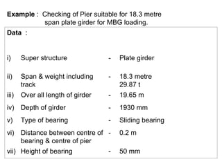
  • 2. Example : Checking of Pier suitable for 18.3 metre span plate girder for MBG loading. Data : i) Super structure - Plate girder ii) Span & weight including track - 18.3 metre 29.87 t iii) Over all length of girder - 19.65 m iv) Depth of girder - 1930 mm v) Type of bearing - Sliding bearing vi) Distance between centre of bearing & centre of pier - 0.2 m vii) Height of bearing - 50 mm
  • 3. viii) Material of const. - M-10 concrete ix) Unit wt. of mass concrete - 2200 to 2400 kg/m3 x) Loading standard - MBG 1987 xi) Angle of internal friction & wt. of soil - 35, 1760 kg/m3 xii) Track structure on approach - 60 kg rail resting on PSC sleeper xiii) Seismic zone - Zone ( V)
  • 5. CHECKING OF PIER SPAN 18.3m FOR MBG LOADING - 1987 AREA AT THE TOP : = 3.66 x 1.5 +(/4) x 1.52 = 7.257 m2 AREA AT 1m DEPTH FROM THE TOP : = 3.66 x 1.537 + (/4) x 1.5372 = 7.481 m2 WIDTH OF SECTION AT 1.5m DEPTH = 1.5705m AREA =3.66 x1.5705+ (/4) x 1.57052 = 7.685 m2 VOLUME OF BED BLOCK = 3.338 m3 WEIGHT OF BED BLOCK = 3.338 x 2.2 = 7.344 t
  • 6. VOLUME OF PIER BETWEEN BED BLOCK AND 1m DEPTH =(7.257+7.481) x 0.54 / 2 = 3.979 m3 VOLUME OF PIER BETWEEN 1m AND 1.5m DEPTH =(7.481+ 7.685) x 0.5 / 2 = 3.792 m3 AREA OF PIER AT 12m DEPTH : = 2.282 x 3.66 + (/4) x 2.2822 = 12.442 m2 VOLUME OF PIER BETWEEN 1.5m AND 12m DEPTH = 3.894 + (12.442 + 7.891) x 10 / 2 = 105.559 m3 BUOYANCY EFFECT : 105.559t x 0.15 5.10.2 SSC
  • 7. TOTAL WEIGHT OF PIER AT 12m DEPTH INCLUDING BUOYANCY EFFECT : = Bed Block +Pier below bed block upto 1.5m+ Wt between 1.5m to 12m depth including buoyancy = 3.338 x 2.2 + (3.979 + 3.792) x 2.4 + (105.559 x2.4) 105.559 x 0.15 = 263.502 t To be checked for single span & double span loading conditions Clause 5.3 c SSC
  • 8. LIVE LOAD : SINGLE SPAN LOADED CONDITION LOADED LENGTH = 19.65 EUDL FOR S.F. = (231.64 222.29) x 0.65 + 222.29 = 227.72 t 5.3 c SSC Appendix XX III BR REACTION = 227.72/2 = 113.86 t DOUBLE SPAN LOADED CONDITION EUDL FOR B.M. L = 2 x 19.8 = 39.6 m EUDL for BM =(376.63-360.53) x 1.6/2 + 360.53 = 373.41 t 5.3 c SSC Appendix XX III BR REACTION = 373.41 / 2 = 186.7 t
  • 9. LONGITUDINAL FORCE Single Span : TE1 = 75.0 BF1 = 50.6 Appendix XX IV BR With Dispersion and Distribution 2.8.3.2 BR TE1 = ( 75 75 x 0.25) x 0.4 = 22.5 2.8.2.4.1 BR BF1 = ( 50.6 16.0 ) x 0.4 = 13.84 For Seismic condition 50% L.F. 2.8.5 BR TE1 =22.5 / 2 = 11.25 t BF1 = 13.84 / 2 = 6.92 t
  • 10. DOUBLE SPAN : With Dispersion and Distribution TE2 = 126.0 BF2 = 80 Appendix XX IV BR TE2 = 126 x 0.75 x 0.4 = 37.8 t BF2 = 80 x 0.75 x 0.4 = 24.0 t For Seismic condition 50% L.F. 2.8.5 BR TE2 = 37.8 / 2 = 18.9 t BF2 = 24.0 / 2 = 12.0 t
  • 11. FORCE DUE TO WATER CURRENT : Water Current flowing parallel to pier P = KAV2 = 35 x (1.5705 + 2.282) x 10.5 x 32 / 2 x 1000 = 6.371 t Clause 5.9.2.1 5.9.2.2 (Tabl e 4) SSC Water Current flowing perpendicular to Pier =35x(1.5705+2.282)+(3.66+2.282)x10.5x32 /2x5x1000 = 3.695 t Clause 5.9.2. 4 SSC Moment at the Base along X-X direction i.e. perpendicular to Pier = 6.371 x 10.5 x 2 / 3 = 44.597 t-m
  • 12. WIND LOAD : Projected area of Girder & track = (1.930 + 0.172 + 0.152) 19.65 = 2.254 x 19.65 = 43.45 m2 Since spacing of girder is not exceeding full depth Hence Factor = 0.25 2.11.3.1(a) BR Projected Area of Girder = 1.25 x 43.45 = 54.3 m2 Lever Arm from C.G. to top of Bed Block = 2.254 / 2 + 0.05 = 1.177 Projected Area of Train (PAT) = ( 4.115 0.6) 19.67 = 69.14 m2 2.11.3.1(b) Note 1 BR Lever Arm from C.G. to Top of Bed Block = 3.515 / 2 + 0.6 + 2.254 +0.05 = 4.641 m
  • 13. SECTIONAL PROPERTIES AT 12m DEPTH AREA = (/4) x 2.2822 + 3.66 x 2.282 = 12.442 m2 Ixx = (1 / 12) x 3.66 x 2.2823 + (/4) x 2.2824 = 4.956 m4 Iyy = (1 / 12) x 2.282x 3.66 3 + 0.2196 x 1.1414 + x 1.141 x (0.5x3.66+0.42x1.141)2 = 31.592 m4
  • 14. SINGLE SPAN LOADED CONDITION : D.L. OF GIRDER + TRACK = 29.87 L.L. REACTION = 108.98 Wt. OF PIER = 263.502 402.352 t MOMENT ALONG X-X AXIS DUE TO L.F. = 22.5(12+0.05) = 271.125 DUE TO WATER CURRENT = 25.865 DUE TO L.L. = 108.98 x 0.2 = 21.796 318.786 t-n MOMENT ALONG Y-Y AXIS DUE TO WATER CURRENT = 44.597 t-m STRESSES : = (402.352/12.442) (318.786/4.956)x(2.282/2) (44.597/31.592)x(3.66/2) = 32.338 73.393 2.583 Max = 108.314 t/m2 Min = - 43.639 t/m2
  • 15. NORMAL LOAD + OCCASSIONAL LOAD (W.L.) DL. OF GIRDER + TRACK = 29.870 LIVE LOAD REACTION = 108.98 Wt. OF PIER = 263.502 402.352 MOMENT ALONG X-X AXIS DUE TO LF = 22.5 ( 12 + 0.05) = 271.125 DUE TO WATER CURRENT = 25.865 DUE TO LL = 21.796 318.786 MOMENT ALONG Y-Y AXIS DUE TO WATER CURRENT = 44.597 DUE TO WIND ON GIRDER 54.3x(1.177+12) 0.15 = 107.327 DUE TO WIND ON TRAIN 69.1 / 2 (4.641=12) x 0.15 = 86.242 238.166 (on one span only)
  • 16. STRESSES : = (402.352/12.442) (318.786/4.956)x(2.282/2) (238.166/31.592)x(3.66/2) = 32.338 73.393 13.796 Max = 119.527 t/m2 Min = -54.945 t/m2
  • 17. DOUBLE SPAN LOADED CONDITION : DL OF GIRDER + TRACK = 29.87 LL REACTION = 176.79 Wt. OF PIER = 263.502 470.162 t MOMENT ALONG X-X AXIS DUE TO L.F. = 30.00(12+0.05) = 361.50 DUE TO WATER CURRENT = 25.865 387.36 t-m MOMENT ALONG Y-Y AXIS DUE TO WATER CURRENT = 44.597 t-m STRESSES : = (470.162/12.442) (387.36/4.956)x(2.282/2) (44.597/31.592)x(3.66/2) = 37.788 88.95 2.583 Max = 37.788+88.95+2.583 = 129.31 t/m2 Min = -53.75 t/m2
  • 18. NORMAL + OCL (DOUBLE SPAN LOADED CONDITION) DL OF GIRDER + TRACK = 29.870 LL REACTION = 176.790 Wt. OF PIER = 263.502 470.162 t MOMENT ALONG X-X AXIS = 387.36 t-m MOMENT ALONG Y-Y AXIS : DUE TO WATER CURRENT = 44.597 DUE TO WIND ON TRAIN 69.1(4.641+12.0) = 172.484 DUE TO WIND OF GIRDER 54.3(1.177+12.0) = 107.327 324.408 t-m STRESSES : = (470.162/12.442) (387.36/4.956)x(2.282/2) (324.408/31.592)x(3.66/2) = 37.788 89.18 18.792 Max = 145.76 t/m2 Min = -70.18 t/m2
  • 19. SEISMIC & HYDRODYNAMIC FORCE When the Horizontal Seismic acting parallel to traffic SEISMIC HORIZONTAL COEFFICIENT h = 硫 I I = 1.0 硫 = 1.2 = 0.08 2.12.4.2 BR 2.12.4.4 BR 2.12.4.3 BR (Table) 2.12.3.3 BR h = 1.2 x 0.08 x1 = 0.096 HYDRO DYNAMIC FORCES F = Ce h Wex Ce = Co-efficient taken from table 5 based on H/R H / R = 10.5 / (5.942 / 2) = 3.534 Ce = (0.735 0.675) x 0.534 + 0.675 = 0.707
  • 20. F = 291.206 x 0.096 x 0.707 = 19.765 t h = H C 1 = H / h = 10.5 / 10.5 = 1.0 C 2 = 1.0 C 3 = 1.0 C 4 = 0.4286 LEVER ARM = C4 H = 0.428 x 10.5 = 4.494 MOMENT = 19.765 x 4.494 = 88.824 t-m Wex = (/4) x 5.9422 x 10.5 x 1 = 291.206 t
  • 21. SEISMIC FORCE IN HORIZONTAL DIRECTION S. No . DESCRIPTION MASS h SEISMI C FORCE LEVE R ARM MOMENT ABOUT X-X 1 GIRDER + TRACK 29.87 0.096 2.8675 13.177 37.79 2 BED BLOCK 7.344 0.096 0.705 11.77 8.298 3 Wt. OF PIER BELOW BED BLOCK 271.992 without Bouancy 5.12.2(a) SSC 0.096 26.111 5.77 150.662 196.752 L.L ignored in case of parallel to traffic 2.12.6 BR
  • 22. SEISMIC FORCE IN VERTICAL DIRECTION S. No. DESCRIPTION MASS v SEISMIC FORCE 1 GIRDER + TRACK 29.87 0.096/2 1.434 2 BED BLOCK 7.344 0.096/2 0.352 3 Wt. OF PIER BELOW BED BLOCK 271.992 0.096/2 13.056 4 LIVE LOAD ( SS ) 108.98 0.096/2 5.231 20.073 5 LIVE LOAD ( DS ) 176.79 0.096/2 8.486
  • 23. When the Horizontal Seismic acting perpendicular to traffic HYDRO DYNAMIC FORCES F = Ce h Wex H / R = 10.5 / (2.282 / 2) = 9.202 Ce = 0.730 Wex = (/4) x 2.2822 x 10.5 x 1 = 42.945 F = 42.945 x 0.096 x 0.730 = 3.03 t LEVER ARM = 0.428 x 10.5 = 4.494 MOMENT = 3.03 x 4.494 = 13.618 t-m
  • 24. HORIZONTAL SEISMIC FORCE S. No . DESCRIPTION MASS h SEISMI C FORCE LEVE R ARM MOMEN T ABOUT X-X 1 GIRDER + TRACK 29.87 0.09 6 2.868 13.177 37.792 2 BED BLOCK 7.344 0.09 6 0.705 11.77 8.298 3 Wt. OF PIER BELOW BED BLOCK 271.99 2 0.09 6 26.11 5.77 150.662 50% LIVE LOAD ( S.S.) 2.12.6 BR 108.98/ 2 0.09 6 5.231 16.641 87.049 283.801 50% LIVE LOAD ( D.S.) 176.79/ 2 0.09 6 8.486 16.641 141.24 337.992
  • 25. VERTICAL EFFECT OF SEISMIC FORCE S. No . DESCRIPTION MASS h SEISMIC FORCE 1 GIRDER + TRACK 29.87 0.048 1.434 2 BED BLOCK 7.344 0.048 0.352 3 Wt. OF PIER BELOW BED BLOCK 271.992 0.048 13.056 4 LIVE LOAD( S.S.) 108.98 0.048 5.231 20.073 D.S. LIVE LOADED CONDITION LIVE LOAD 176.79 0.048 8.486 23.328
  • 26. STRESS CALCULATIONS : SINGLE SPAN When the Seismic Force acting parallel to Traffic DL OF GIRDER + TRACK = 29.870 LL REACTION = 108.98 Wt. OF PIER = 263.502 LESS SEISMIC FORCE = - 20.073 382.279 t MOMENT ABOUT X-X AXIS DUE TO 50% L.F. = ( 22.5 x 0.5) x 12.05 = 135.563 t-m DUE TO WATER CURRENT = 25.865 t-m DUE TO L.L. = 21.796 t-m DUE TO SEISMIC FORCE = 196.752 DUE TO HYDRODYNAMIC FORCE = 088.824 468.800 t-m MOMENT ABOUT Y-Y AXIS DUE TO WATER CURRENT = 44.597 t-m
  • 27. STRESSES = (382.279/12.442) (468.80/4.956)x(2.282/2) (44.597/31.592)x(3.66/2) = 30.725 107.93 2.583 Max. = 30.725 + 107.93 + 2.583 = 141.238 t/m2 Max. Stress shall be 144.5 t/m2 if vertical component of seismic force is taken downwards. Min. = 30.725 - 107.93 2.583 = ( -) 79.788 t/m2
  • 28. When the Seismic Force acting parallel to Traffic : DL OF GIRDER + TRACK = 29.870 LL REACTION = 108.98 Wt. OF PIER = 263.502 LESS SEISMIC FORCE = - 20.073 382.279 t MOMENT ABOUT X-X AXIS DUE TO 50% L.F. = ( 22.5 x 0.5) x 12.05 = 135.563 t-m DUE TO WATER CURRENT = 25.865 t-m DUE TO L.L. = 21.796 t-m 183.224 t-m MOMENT ABOUT Y-Y AXIS DUE TO WATER CURRENT = 44.597 t-m DUE TO SEISMIC FORCE = 283.801 t-m DUE TO HYDRODYNAMIC FORCE = 13.618 t-m TOTAL 342.016 t-m
  • 29. STRESSES = (382.279/12.442) (183.224/4.956)x(2.282/2) (342.016/31.592)x(3.66/2) = 30.725 42.183 19.812 Max. = 30.725 + 42.183 + 19.812 = 92.72 t/m2 Min. = 30.725 42.183 19.812 = ( -) 31.27 t/m2
  • 30. DOUBLE SPAN : When the Seismic Force acting parallel to traffic : DL OF GIRDER + TRACK = 29.870 LL REACTION = 176.79 Wt. OF PIER = 263.502 LESS SEISMIC FORCE = - 23.328 446.834 t MOMENT ABOUT X-X AXIS DUE TO 50% L.F. = 15.00 x 12.05 = 180.75 t-m DUE TO WATER CURRENT = 25.865 t-m DUE TO SEISMIC FORCE = 196.752 t-m DUE TO HYDRODYNAMIC FORCE = 88.824 492.191 t-m MOMENT ABOUT Y-Y AXIS DUE TO WATER CURRENT = 44.597 t-m
  • 31. STRESSES = (446.834/12.442) (492.791/4.956)x(2.282/2) (44.597/31.592)x(3.66/2) = 35.913 113.315 2.583 Max. = 35.913 + 113.315 + 2.583 = 151.811 t/m2 Min. = 35.913 113.315 2.583 = ( -) 79.985 t/m2
  • 32. When the Seismic Force acting perpendicular to traffic : DL OF GIRDER + TRACK = 29.870 LL REACTION = 176.79 Wt. OF PIER = 263.502 LESS SEISMIC FORCE = - 23.328 446.834 t MOMENT ABOUT X-X AXIS DUE TO 50% L.F. = 15.00 x 12.05 = 180.75 t-m DUE TO WATER CURRENT = 25.865 t-m 1.t-m MOMENT ABOUT Y-Y AXIS DUE TO WATER CURRENT = 44.597 t-m DUE TO SEISMIC FORCE = 337.992 t-m DUE TO HYDRODYNAMIC FORCE = 13.614
  • 33. STRESSES = (446.834/12.442) (206.615/4.956)x(2.282/2) (396.207/31.592)x(3.66/2) = 35.913 47.568 22.951 Max. = 35.913 + 47.568 + 22.951 = 106.432 t/m2 Min. = 35.913 47.568 22.951 = ( -) 34.606 t/m2