
PNEUMATIC CONTROL SYSTEM IN CONTROL ENGINEERING
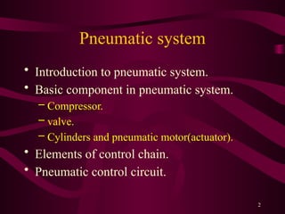
- 2. 2 Pneumatic system ŌĆó Introduction to pneumatic system. ŌĆó Basic component in pneumatic system. ŌĆō Compressor. ŌĆō valve. ŌĆō Cylinders and pneumatic motor(actuator). ŌĆó Elements of control chain. ŌĆó Pneumatic control circuit.
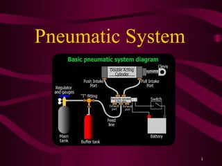
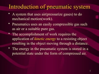
- 3. 3 Introduction of pneumatic system ŌĆó A system that uses air(pressurize gases) to do mechanical motion(work). ŌĆó Pneumatics uses an easily compressible gas such as air or a suitable pure gas. ŌĆó The accomplishment of work requires the application of kinetic energy to a resisting object resulting in the object moving through a distance. ŌĆó The energy in the pneumatic system is stored in a potential state under the form of compressed air.
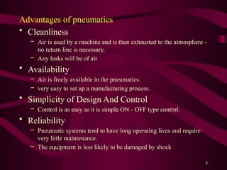
- 4. 4 Advantages of pneumatics ŌĆó Cleanliness ŌĆō Air is used by a machine and is then exhausted to the atmosphere - no return line is necessary. ŌĆō Any leaks will be of air ŌĆó Availability ŌĆō Air is freely available in the pneumatics. ŌĆō very easy to set up a manufacturing process. ŌĆó Simplicity of Design And Control ŌĆō Control is as easy as it is simple ON - OFF type control. ŌĆó Reliability ŌĆō Pneumatic systems tend to have long operating lives and require very little maintenance. ŌĆō The equipment is less likely to be damaged by shock
- 5. 5 ŌĆó Storage ŌĆō Compressed Gas can be stored, allowing the use of machines when electrical power is lost. ŌĆó Safety ŌĆō Very small fire hazards (compared to hydraulic oil). ŌĆō Machines can be designed to be overload safe.
- 6. 6 Disadvantages of pneumatic system are: ŌĆó Low accuracy and control limitation because of compressibility. ŌĆó Noise pollution. ŌĆó Leakage of air can be of concern. ŌĆó Additional drying and filtering may be required. ŌĆó Difficult speed control.
- 7. 7 Basic component in the pneumatic system ŌĆó Air Compressor unit. ŌĆó Air Compressors compress air from atmosphere to higher pressures. There are two (2) basic types of compressors in use today: ŌĆō Positive displacement (Intermittent Flow) ŌĆō Dynamic (Continuous-flow) ŌĆó Air is pumped through a non-return valve into a strong metal tank called a receiver.
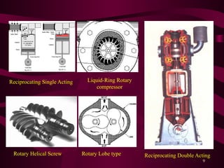
- 8. 8 ŌĆó The positive displacement type of compressor uses a squeezing effect to force gas molecules into a smaller space. ŌĆó The dynamic compressor applies mechanical force to gas to increase its velocity, which is the converted to pressure. ŌĆó Several types of positive displacement compressor are: ŌĆō Reciprocating Single Acting ŌĆō Reciprocating Double Acting ŌĆō Rotary Helical Screw ŌĆō Liquid-Ring Rotary compressor ŌĆō Rotary Lobe type
- 9. 9 Reciprocating Single Acting Rotary Lobe type Rotary Helical Screw Liquid-Ring Rotary compressor Reciprocating Double Acting
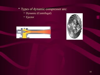
- 10. 10 ŌĆó Types of dynamic compressor are: ŌĆō Dynamic (Centrifugal) ŌĆō Ejector
- 11. 11 ŌĆó Valve ŌĆō Several types of valve consist in pneumatic system: ŌĆó Safety relief valve. ŌĆó Flow control valve. ŌĆó Shuttle valve. ŌĆó Check valve. ŌĆó Directional control valve.
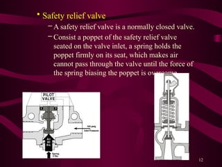
- 12. 12 ŌĆó Safety relief valve ŌĆō A safety relief valve is a normally closed valve. ŌĆō Consist a poppet of the safety relief valve seated on the valve inlet, a spring holds the poppet firmly on its seat, which makes air cannot pass through the valve until the force of the spring biasing the poppet is overcome.
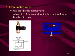
- 13. 13 ŌĆó Flow control valve. ŌĆō Also called speed control valve. ŌĆō Allows free flow in one direction but restricts flow in the other direction.
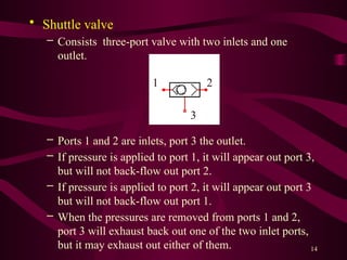
- 14. 14 ŌĆó Shuttle valve ŌĆō Consists three-port valve with two inlets and one outlet. ŌĆō Ports 1 and 2 are inlets, port 3 the outlet. ŌĆō If pressure is applied to port 1, it will appear out port 3, but will not back-flow out port 2. ŌĆō If pressure is applied to port 2, it will appear out port 3 but will not back-flow out port 1. ŌĆō When the pressures are removed from ports 1 and 2, port 3 will exhaust back out one of the two inlet ports, but it may exhaust out either of them. 1 2 3
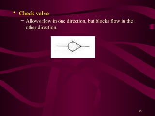
- 15. 15 ŌĆó Check valve ŌĆō Allows flow in one direction, but blocks flow in the other direction.
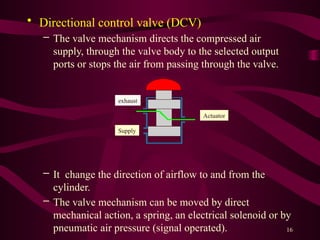
- 16. 16 ŌĆó Directional control valve (DCV) ŌĆō The valve mechanism directs the compressed air supply, through the valve body to the selected output ports or stops the air from passing through the valve. ŌĆō It change the direction of airflow to and from the cylinder. ŌĆō The valve mechanism can be moved by direct mechanical action, a spring, an electrical solenoid or by pneumatic air pressure (signal operated). Supply Actuator exhaust
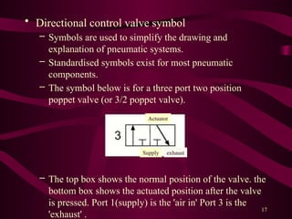
- 17. 17 ŌĆó Directional control valve symbol ŌĆō Symbols are used to simplify the drawing and explanation of pneumatic systems. ŌĆō Standardised symbols exist for most pneumatic components. ŌĆō The symbol below is for a three port two position poppet valve (or 3/2 poppet valve). ŌĆō The top box shows the normal position of the valve. the bottom box shows the actuated position after the valve is pressed. Port 1(supply) is the 'air in' Port 3 is the 'exhaust' . Supply Actuator exhaust
- 18. 18 ŌĆō The shape on the end of the symbols show how the internal mechanism is operated. Plunger Solenoid Pedal Level Push button Roller trip Spring Plunger
- 19. 19
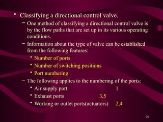
- 20. 20 ŌĆó Classifying a directional control valve. ŌĆō One method of classifying a directional control valve is by the flow paths that are set up in its various operating conditions. ŌĆō Information about the type of valve can be established from the following features: ŌĆó Number of ports ŌĆó Number of switching positions ŌĆó Port numbering ŌĆō The following applies to the numbering of the ports: ŌĆó Air supply port 1 ŌĆó Exhaust ports 3,5 ŌĆó Working or outlet ports(actuators) 2,4
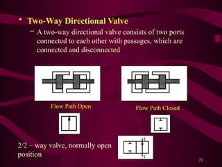
- 21. 21 ŌĆó Two-Way Directional Valve ŌĆō A two-way directional valve consists of two ports connected to each other with passages, which are connected and disconnected Flow Path Open Flow Path Closed 2/2 ŌĆō way valve, normally open position
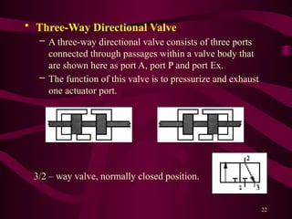
- 22. 22 ŌĆó Three-Way Directional Valve ŌĆō A three-way directional valve consists of three ports connected through passages within a valve body that are shown here as port A, port P and port Ex. ŌĆō The function of this valve is to pressurize and exhaust one actuator port. 3/2 ŌĆō way valve, normally closed position.
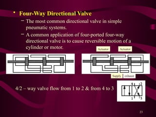
- 23. 23 ŌĆó Four-Way Directional Valve ŌĆō The most common directional valve in simple pneumatic systems. ŌĆō A common application of four-ported four-way directional valve is to cause reversible motion of a cylinder or motor. 4/2 ŌĆō way valve flow from 1 to 2 & from 4 to 3 Supply Actuator exhaust Actuator
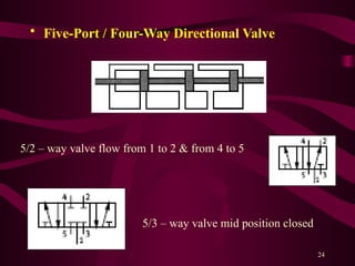
- 24. 24 ŌĆó Five-Port / Four-Way Directional Valve 5/2 ŌĆō way valve flow from 1 to 2 & from 4 to 5 5/3 ŌĆō way valve mid position closed
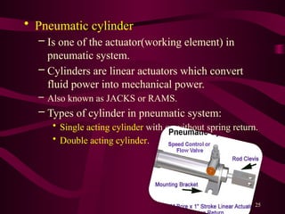
- 25. 25 ŌĆó Pneumatic cylinder ŌĆō Is one of the actuator(working element) in pneumatic system. ŌĆō Cylinders are linear actuators which convert fluid power into mechanical power. ŌĆō Also known as JACKS or RAMS. ŌĆō Types of cylinder in pneumatic system: ŌĆó Single acting cylinder with or without spring return. ŌĆó Double acting cylinder.
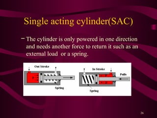
- 26. 26 Single acting cylinder(SAC) ŌĆō The cylinder is only powered in one direction and needs another force to return it such as an external load or a spring.
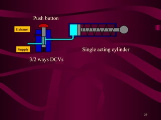
- 27. 27 3/2 ways DCVs Single acting cylinder Push button Supply Exhaust
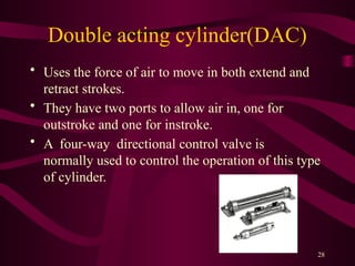
- 28. 28 Double acting cylinder(DAC) ŌĆó Uses the force of air to move in both extend and retract strokes. ŌĆó They have two ports to allow air in, one for outstroke and one for instroke. ŌĆó A four-way directional control valve is normally used to control the operation of this type of cylinder.
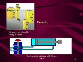
- 29. 29 Example; Double acting cylinder with 5/2 wa y DCV Double acting cylinder with 3/2 way DCV Several types of double acting cylinder
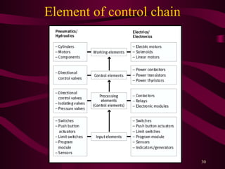
- 30. 30 Element of control chain
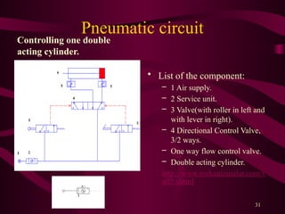
- 31. 31 Pneumatic circuit Controlling one double acting cylinder. ŌĆó List of the component: ŌĆō 1 Air supply. ŌĆō 2 Service unit. ŌĆō 3 Valve(with roller in left and with lever in right). ŌĆō 4 Directional Control Valve, 3/2 ways. ŌĆō One way flow control valve. ŌĆō Double acting cylinder. http://www.mekanizmalar.com/v alf5.shtml
- 32. 32
- 33. 33
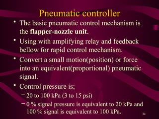
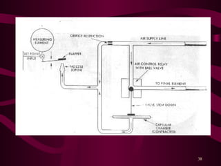
- 34. 34 Pneumatic controller ŌĆó The basic pneumatic control mechanism is the flapper-nozzle unit. ŌĆó Using with amplifying relay and feedback bellow for rapid control mechanism. ŌĆó Convert a small motion(position) or force into an equivalent(proportional) pneumatic signal. ŌĆó Control pressure is; ŌĆō 20 to 100 kPa (3 to 15 psi) ŌĆō 0 % signal pressure is equivalent to 20 kPa and 100 % signal is equivalent to 100 kPa.
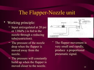
- 35. 35 The Flapper-Nozzle unit ŌĆó Working principle: ŌĆō Input air(regulated at 20 psi or 138kPa ) is fed to the nozzle through a reducing tube(restriction). ŌĆō The pressure of the nozzle drop when the flapper is moved away from the nozzle. ŌĆō The pressure will constantly build up when the flapper is moved closer to the nozzle. ŌĆŠ The flapper movement is very small and rapidly, produce a proportional pneumatic signal.
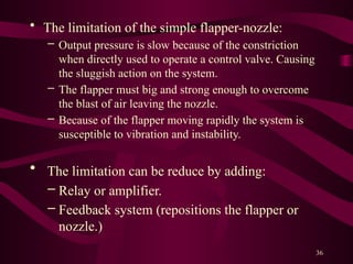
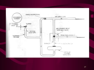
- 36. 36 ŌĆó The limitation of the simple flapper-nozzle: ŌĆō Output pressure is slow because of the constriction when directly used to operate a control valve. Causing the sluggish action on the system. ŌĆō The flapper must big and strong enough to overcome the blast of air leaving the nozzle. ŌĆō Because of the flapper moving rapidly the system is susceptible to vibration and instability. ŌĆó The limitation can be reduce by adding: ŌĆō Relay or amplifier. ŌĆō Feedback system (repositions the flapper or nozzle.)
- 37. 37
- 38. 38
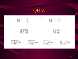
- 39. 39 QUIZ